|
Network Notepad
Freeware Edition Help |
The Tool Bar

| |
 Back and Forward buttons. These are used to move back and forth through
previously loaded diagrams.
Back and Forward buttons. These are used to move back and forth through
previously loaded diagrams. |
|
 Auto Align Button. When selected, objects are automatically aligned horizontally
or vertically with the previously pasted object.
Auto Align Button. When selected, objects are automatically aligned horizontally
or vertically with the previously pasted object. |
| |
 Open a network diagram file.
 |
|
 Send to Back, Bring to Front Buttons. These change the order that objects are
drawn.
Send to Back, Bring to Front Buttons. These change the order that objects are
drawn. |
| |
 Save the current file.
 |
|
 Connection Points Button. Selects between linking to a single point on an object
or linking to any part of an object.
Connection Points Button. Selects between linking to a single point on an object
or linking to any part of an object. |
| |
 Print Diagram
 |
|
 Link Button. Toggles link mode on and off. Left click on objects to link them.
 |
| |
 Object Libraries Button. This button opens the current Object Library and
displays available objects to use in the diagram.
Object Libraries Button. This button opens the current Object Library and
displays available objects to use in the diagram. |
|
 Link Selection Drop Down List.
 |
| |
 Cut button. Delete selected objects and place on clipboard.
 |
|
 Unlink Button. Removes links between selected objects
 |
| |
 Copy Button. Copies selected objects to the Network Notepad clipboard.
 |
|
 Zoom Out.
 |
| |
 Paste Button. Switches to paste mode. Left Click will paste objects from
the Network Notepad clipboard or selected from the Object Library.
Paste Button. Switches to paste mode. Left Click will paste objects from
the Network Notepad clipboard or selected from the Object Library. |
|
 IP Addresses Button. Toggles the display of IP Addresses.
 |
| |
 Delete Button. Delete selected objects.
 |
|
 Programmable function buttons.
 |
| |
 Text Mode Button. Toggles text mode on and off. Left click will position
a text cursor at the current mouse position.
Text Mode Button. Toggles text mode on and off. Left click will position
a text cursor at the current mouse position. |
|
 Exit
Button. Exit
Button. |
Navigating
To pan around diagram, hold down the right mouse button and move the mouse
(The mouse pointer needs to be position over the background of the diagram).
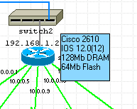
To follow a link to another diagram - Right click the object and select
"Goto next diagram". Objects which link to other diagrams have a blue caption.
The tool bar back and forward buttons may also be used to jump to the
previous or next diagram.
Adding Objects To A Diagram
Click the Object Libraries Button
to display the current Object Library.
Drag and drop Objects from the Library to the diagram.
You may also paste Library objects by selecting the object from the
library and then closing or minimising it.
Point the cross hair where you want to place the objects.
Click the Paste Button again to finish pasting.
To automatically hide the Object Library whenever you select a new
object, enable "Auto Hide" in the setup dialogue.
Tip: Double right click the background to toggle
the last used mode (Paste, Text, or Link) off and on.
Cutting And Deleting Objects From A Diagram
Highlight the objects you wish to cut or delete by left clicking them and
then hit the Cut Button
to place them on the clipboard. Alternatively hit the Delete Button  to remove them completely.
Pressing SHIFT+Delete on the keyboard is another
way to delete selected items.
Selecting/ Deselecting Single/ Multiple objects
Objects need to be selected (Red highlight) and deselected for cutting
and pasting. To select an object, left click on it.
To select or deselect multiple objects at once, drag a "rubber band"
around them with the left mouse button.
You must start selection with the mouse pointer positioned over a blank
piece of background.
To select or unselect additional objects, hold down the CTRL key
while selecting.
To select no objects from the main ring choose Edit and then Select
None, or type CTRL-A.
Clicking the background of the diagram also resets all selections.
Aligning Objects
To align objects, select them and choose Format and Align Horizontal or
Align Vertical from the Ring Menu.
When pasting objects and drawing links, objects and lines are automatically
aligned if the Auto Align button
is selected.
Resizing Objects
Use Shift + and Shift - to adjust the size of the current
object.
From the ring menu select Format > Resize Mode and then either Both, Horizontal
or Vertical to set the quick resize function.
Objects can also be resized in the Object Properties
form.
|
|
Linking Objects
To link two objects, firstly use the Link Selection Box to
choose the desired type of Link.
Left Click the link button ,
the mouse pointer will indicate you are in Link Mode. Left Click on pairs
of objects to join them.
You may also Right Click an object and choose "Link" to enter link
mode.
To finish linking objects, click the link button
again.
Clicking the background whilst in link mode enables you to form elbows
and bends in links.
|
|
Tip: Double right click the background to toggle
the last used mode (Paste, Text, or Link) off and on.
|
|
|
Linking To Part of An Object
By default, links point to the centre of an object. You may link to any
part of an object using the Connection Points Option from the Format menu
or clicking the Connection Points Button .
Select Connection Points - Unlimited to link to any part of an object
or Connection Points - 1 to return to the default setting.
|
|
|
Linking To Part Of A Background Object
By setting an object to a backgound layer and setting Connection Points to unlimited
you may link to parts of the object, with links shown on top of the object.
See Object Properties on how to set an object
to a background layer.
See also: Customizing Link Styles
|
|
Unlinking Objects
To remove links between objects, select the objects which are linked and
then click the Unlink Button .
Moving and Copying Objects
To move objects, first select the objects you
wish to move (Red highlight) and then hold down the Shift Key
while dragging one of the objects to the
new position.
To copy objects, select them and then click then Copy Button.
Click the Paste Button
to enter Paste Mode and the position the cross hair and left click to paste
copies of the objects. To finish pasting, click the Paste Button
again.
Nudging Objects
To nudge all selected objects hold the Shift and press one of the cursor keys.
Changing The Name (Or IP Address) Of An Object
To change the name of an object or change it's IP address, Double
Left Click on current name or IP address and type in the new details. Press
Enter to complete.
You may also change these details by right clicking on the object and
selecting "Properties". See Object Properties
below.
When specifying IP addresses, you may include additional information,
eg. subnet mask, following a "/" character. Eg. 192.168.55.2 /28 or 192.168.55.2
/255.255.255.240. The "/" character and any text which follows is ignored
when using the programmable function buttons.
You may insert a Carriage Return in an Object or IP Label using Shift + Enter.
Adding Text To A Diagram
| |
Click the Text Mode Button
and then Left Click when the cross hair 1
is where you want the text to appear.
The Text Mode button will indicate you are in Text Mode 2.
To finish entering text, click the Text Mode button again or press
the Escape key.
Tip: Double right click the background to toggle the last used mode
(Paste, Text, or Link) off and on.
|
|
Editing Text
To Edit text in text box, double click on it.. The Text Mode button will
indicate you are in Text Mode.
Press ESC to finish editing the text, or click the text mode button
on the tool bar.
To delete a Text Box, double click it and then hit backspace. Press
ESC or click the text mode button to complete.
Changing Text Font And Colour
To change the font or colour of a Textbox on the diagram., right click
the text and select Font or Colour.
To change the current default font or colour, from the ring Menu select
Format and then either Text Font or Text Colour
You may also alter the text font or colour whilst editing text.
Moving Text
To move text, hold the SHIFT key down and drag the text.
|
|
|
Adding Float Text To Objects
Information can be displayed when the pointer is held over an object for
a few seconds.
To Add or Edit Float Text, right click the object and select Edit Float
Text.
Enter text into the Float Text entry box and hit escape when complete.
|
Adding Horizontal And Vertical Backbones
| |
To insert a horizontal or vertical backbone, select Insert from the
Ring Menu and then either horizontal or vertical backbone.
Position the cross hair roughly where you want the centre of the backbone
to be and click the left mouse button.
Click the Paste Mode
button to finish adding backbones.
|
|
Resizing And Moving Backbones
To resize a backbone, position the cursor over either end then hold the
left mouse button down to drag the backbone larger or smaller.
To move a backbone, hold the shift key down whilst dragging the backbone
to a new position.
Alternative Backbone Styles
| |
Use Format Link Styles to change the width of the "Backbone"
link style to 16.
|
|
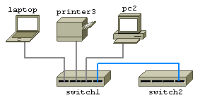
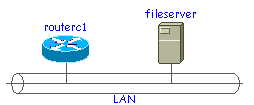
Linking An Object To A Backbone
To link an object to a backbone, click on the link mode button
and then join the backbone to the object. It does not matter what Link
Type has been selected when doing this.
Hiding IP Addresses
To Reveal or Hide IP addresses, toggle the IP Address Button .
Using The Programable Function Buttons
The programmable function buttons
can be programmed to execute external applications. The application
may be supplied with the IP address or hostname of the most recently clicked
object. F1 for instance is pre-programmed to Telnet to the IP address of
the most recently clicked object.
The 5 programmable function buttons are also present in the pop up
menu when you right click an object.
|
|
Customising The Programmable Function Buttons
The programmable function button definitions are accessed in the Setup
screen. The following Network Notepad keywords may be included in the definitions:
$IPADDRESS - is substituted for the most recently clicked object's
principal IP address.
$HOSTNAME - is substituted with the most recently clicked object's
hostname.
$EXPLORE - invokes an instance of internet explorer.
eg. $explore $ipaddress...... to browse the object by
ipaddress.
$BROWSE -
invokes the default browser/application.
eg. $browse $hostname.doc.....will try and open for
example "router1.doc" in whatever
application is configured to handle .doc files.
Copy2Clipboard - Copies the resolved definition to the windows clipboard.
$FILENAME - is substituted for the current diagram's filename (.ndg).
Other Examples:
Use
SSH to connect to a device using Putty.
"C:\Program Files\putty\putty.exe -ssh $IPADDRESS"
Remote control a device using VNC.
"C:\Program Files\ORL\vnc\vncviewer $IPADDRESS"
Remote Desktop.
"C:\windows\system32\mstsc.exe /v:$IPADDRESS"
|
|
TIP
A Traceroute Function Window That Doesn't
Close Automatically.
Create a traceroute.bat file in the Network Notepad folder
which contains:
@echo off
tracert -d %1
pause
Define the function button as:
traceroute.bat $ipaddress |
| |
|
| |
|
Printing
To print a diagram use the print button on the toolbar. If you have a large canvas size
the objects will appear small when printed. Drag the canvas smaller or reduce
the Canvas width and height in the Diagram Properties form to make the
objects to appear larger when printed.
The Zoom Out button on the toolbar functions similar to a Print Preview function
and enables you to see how the page will look when printed.
The ratio of height to width of the Canvas also determines whether the page is
printed in landscape or portrait mode. If you ensure the ratio setting shown in
the Diagram Properties form is 1.414 then the Canvas will match an A4 page in
landscape mode. A ratio of 0.707 matches an A4 page in portrait mode.
|
|
Searching Diagrams
To search a diagram, press CTRL-F and enter some text to find.
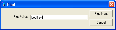
Use F3 to Find Next.
Tip: Network Notepad Files
are stored as plain text. Use Windows "Search for Files" to scan through all
your diagrams and find what you are looking for.
Customizing Link Styles
To Customize the link styles select Format from the ring menu and then
Link Styles.
Select a Link Type to customize from the Link Type drop down
box or select New Link Type to define a new link style.
|
|
|
|
|
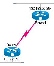
Format: Choose between Line, Lightning, Lightning2, Arrow
and Curve Styles. For the Lightning style to be effective set the width
to 14 or more.
Colour: Select Colour of Link
Style: Select from Opaque and various dashed line styles.
Width: Width of Link.
Angle: Selects the angle for arrow heads.
Length: Selects the size of arrow heads.
Style2: 1 for Solid arrow heads. 0 for Open arrowheads.
Endcap: Selects the endcap style for lines.
Join: Selects the join style for lines.
The Save, Load and Load Default options may be
used to load and save a selection of link styles. Link styles are also
saved with diagrams.
|
|
|
Curve link styles
Curved link styles use one or two link nodes to act as control points for
the curve. From the ring menu select "Options" and "Show Link nodes" to
display link nodes while you are drawing curves.
Click the first object, click the background to place the first control
point, click the background again to create a second control point and then
click the second object to complete the link.
|
|
|
THE
OBJECT PROPERTIES FORM |
| |
The Object Properties Form is divided into three areas:
1. A snapshot of the object and surrounding diagram.
2. Object properties.
3. Links Table.
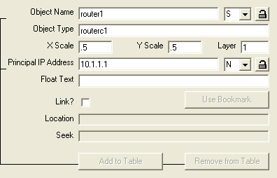
Object Properties
Object Name: The name of the object + relative position of label.
Object Type: Name of the object as shown in the Object Library.
X/Y Scale: Used to enlarge or reduce the Bitmap.
Layer: Sets the order which the object is drawn. The background and grid
lines are drawn first followed by objects in layers 5 to 3, then links are drawn
and then objects in layers 2 to 0 are uppermost. The "Send to Back" and "Bring
to Front" buttons on the toolbar moves the selected objects through the different
layers.
Principal IP Address: Specifies the IP address used by the programmable
function buttons.
Float Text: Text which appears when the cursor hovers over an
object.
|
 |
| |
|
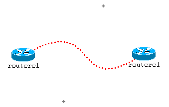
Linking Diagrams
Diagrams may be linked together such that one or more special objects in a
diagram provide a link to other diagram files. To follow a link to another
diagram, right click the object and select "Goto next diagram". Configure an
object to be a link to another diagram, in the Object Properties form using
the following settings:
Link to another Diagram?: This tick box enables the "Goto next diagram"
option when this object is right clicked.
Location: Filename of next diagram (include .ndg extension).
Seek: Some text to seek when the next diagram is loaded.
Use bookmark: Completes the Location and Seek fields with the
last bookmarked location (Edit > bookmark).
|
Drag And Drop Method For Linking Diagrams
Another way to create a link to a diagram is to drag and drop the .ndg file you
want to link to on to the canvas of the current diagram. This adds an object
which acts as the link as stated above.
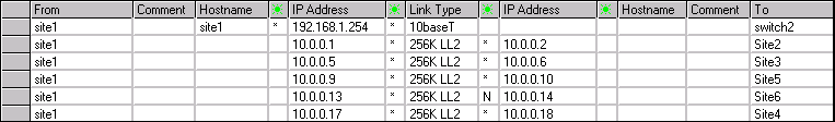
The Links Table
| |
The links table shows a table of all the connections to an object.
Clicking any column heading sorts the table by that particular column.
An IP Address, Hostname and Comment may be entered for each end of
each link.
The  columns are drop-down boxes from which you choose the display position
relative the object for the IP Address or Hostname.
columns are drop-down boxes from which you choose the display position
relative the object for the IP Address or Hostname.
The "Add to table"/ "Remove from table" buttons are used to transfer
or remove the object's principal IP address and Hostname to/from the table.
To enable this button, you must highlight one of the rows by clicking column
0.
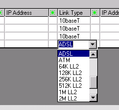
Changing Link Types
To change a link type for any of the connections, click a box in the Link
Type column and choose the new link style from the drop down list.
|
|
| |
Click the Object Library button
on the main window to display the Object Library.
Select different libraries from the Drop down list or use "File","Open".
All libraries should reside in the "objects" folder.
Right clicking an object allows you to change an objects default name,
filename and X/Y scale.
Adding New Objects To The Object Library Form
There are two methods for adding new objects to a library. The first
way is to drag a .ico, .bmp, or .wmf
file on to a blank part of the Object library form.
To rename an object, right click it and select "Rename Object" or double click
the object's label. You also have the option to rename the bitmap filename, and resize the
object by right-clicking it.
Another way to add new objects is by copying a
bitmap to the Windows Clipboard using Edit>Copy from another Windows
application. Select
"Edit" and "Paste Image from Clipboard to Object Library" to add the new
icon.
This method usually copies the image in .bmp or .wmf format. Note .bmp files do not support
background transparency. This method worked particularly well for copying
.wmf icons from Powerpoint and is how the images shown to the right were collected.
Use "File","Save Object Library" to save the updated Object Library file.
|
Visit the Download Page to get more Objects like
these. |
Tip: .ico and .wmf files support a transparent
background colour.
|
Deleting Objects From The Object Library Form
To delete an object from the current Object Library, select the object
followed by "Edit" and "Cut Image from Object Library".
Auto-Hiding The Object Library Form
To auto-hide the Object Library Form whenever an object is selected select
"File" and "Auto-hide".
Creating New Object Library Files
File>New is available in version 2.4.2 to create a new, blank Object Library
file. Paste new object images as explained previously and then use File
> Save As to save the new Object Library.
Sharing Object Library Files
A workgroup Object Library (Folder) may be specified in the main setup
form. Network Notepad will use this library when the shared drive is available.
Otherwise it will use the default local copy.
To set this up initially, copy contents of the local objects directory
to the shared directory.
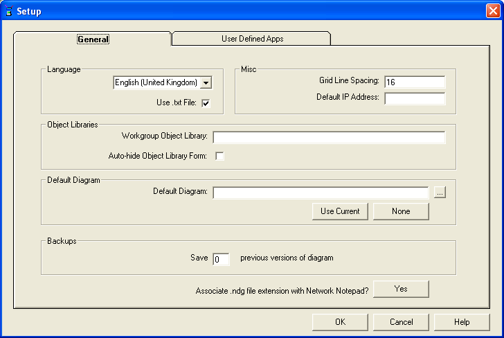
The Setup Form
General Settings: Language: Select the Language used for Network Notepad.
The only items on the Setup Form which have not already been mentioned
are as follows:
Default IP Address. A partial or complete IP Address which will
be applied to all new objects added to the diagram.
Grid Line Spacing. Sets the spacing for grid lines when grid
lines option is switched on ("Options","Grid Lines").
Default Diagram: Sets the diagram loaded by default if no diagram is
specified. Use the ellipses button browse for a file or the "Use Current"
make the currently open diagram the default diagram. The "None" button specifies
no default diagram.
Save X previous versions of diagram. This option keeps the specified
number of previously saved versions of the diagram in a "netpadsafe" folder.
This option is present only in Beta versions.
Associate .ndg extension with Network Notepad. Let's you open
.ndg files by double clicking them. See below.
User Defined Apps:
For information on the User Defined Apps, see Using
The Programmable Function Buttons.
|
The
Diagram Properties Form |
|
|
The Diagram Properties Form
The Diagram Properties Form is accessed from the main ring menu File >
Edit Diagram Properties.
The Diagram Name, Notes1 and Notes2 are text fields
stored in the diagram.
Hosts File: Specifies the file used to supply IP addresses.
See Below.
Canvas Width and Canvas Height specify the size of the canvas.
There is a limitation in the current release whereby if you attempt to make the
Canvas too large you may get memory resource problems. This shows up
particularly when you try to export to a bitmap file, print or use the zoom
button. You may get a blank form or an error when this happens. You have been
warned!
Backdrop: Specify an image file for the Backdrop of the diagram.
Forground Colour and Background Colour: Sets the colours
used for Object Name and IP Labels.
Link Text Colour: Selects the colour for text used to highlight
objects which link to another diagram.
Float Text Foreground and Background Colours: Sets the colours
used for Float Text.
Make These The Default: Sets the defaults for new diagrams.
|
 |
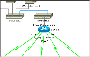
Using A Hosts File To Supply IP Addresses
A hosts file may be used to supply IP addresses to all objects in a diagram
with names which match entries in the hosts file.
1. From the ring menu, select File and then Edit Diagram Properties.
2. Enter the filename of the hosts file in the field provided and hit
OK.
3. From the ring menu, select Options and then Refresh IP Addresses
to transfer IP addresses to the diagram.
Hosts File Format
The format for each line in the hosts file should be as follows:
IP Address <TAB(s) or SPACE(s)> Hostname <Rest of line ignored><CRLF
or just CR to terminate line>
Adding A Backdrop Image
There is only limited support for this at the moment.
To add a backdrop image, use File Edit Source and carefully(!) add
a line to the end of the file using the following format and save the file
back.
backdrop <filename>
eg.
backdrop c:\images\uk.jpg
The image file is stretched vertically and horizontally to fill the
canvas.
The following file formats can be used: jpg, bmp and wmf.
Export To Bitmap Graphics File
To export a diagram as a bitmap file, from the ring menu, select File
and then Export To Bitmap Graphics File. Enter a suitable filename when prompted.
The following bitmap file types can be selected from drop-down list: .bmp,
.gif and .png.
Associating .ndg File Extension With Netpad.exe
There is a button in the Setup Form which automatically associates the
.ndg extension with netpad.exe so that Network Notepad is launched on double
clicking a .ndg file.
Aternatively the association may be set up as follows:
Open a folder and select Tools > Folder Options > File Types. Select
the .ndg file extension or add it if not present.
Select Advanced and add an "open" action if not already present.
Edit and ensure Action is set to "open" and Application used to perform
action is set to "C:\Program
Files\Network Notepad\netpad.exe" %1
(Or path to where Network Notepad is installed on your system).
Setting A Default Diagram
You may configure a default diagram to be displayed when Network Notepad is
run. The default diagram is configured in the Setup Form.
Report A Bug
If you find a bug, please email details to
jason@networknotepad.com
|
|