Keyboard and Mouse Controls
The Toolbar
|
|||||||||||||||||||||||||||||||||||||||||||||||||||||||||||||||||||||||||||||||||||||||||||||||||||||||||||||||||||||||||||||||||||||||||||||||||||||||||||||||||||||||||||||||||||||||||||||||||||||||||||||||||||||||||||||||||||||||||||||||||||||||||||||||||||||||||||||||||||||||||||||||||||||||||||||||||||||||||||||||||||||||||||||||||||||||||||||||||||||||||||||||||||||||||||||||||||||||||||||||||||||||||||||||||||||||||||||||||||||||||||||||||||||||||||||||||||||||||||||||||||||||||||||||||||||||||||||||||||||||||||||||||||||||||||||||||||||||||||||||||||||||||||||||||||||||||||||||||||||||||||||||||||||||||||||||||||||||||||||||||||||||||||||||||||

|
To link objects, firstly use the Link Style Dropdown Box Click the link button You may also right-click an object and choose "Link" to enter link mode. To finish linking objects, click the link button Clicking the background whilst in link mode enables you to form joins (elbows) in links (See also the link break feature). Clicking an existing link automatically sets the Link Style Dropdown Box to the matching link style. To modify or create link styles see Formatting Link Styles. |
 |
Tip: Double right click the background to toggle the last used mode (Paste, Text, or Link) off and on.
Link Align
|
|
 |
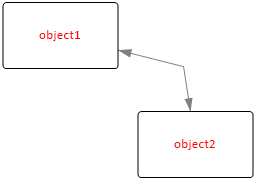
Moving A Link From One Object To Another
|
|
 |
Layers (Drawing Order)
|
|
|
Background Objects
Setting an object to be a background object in the Object Properties form enables you to draw multi-segment links over the top of an object without connecting to it.
Unlinking Objects
To remove links between objects, right-click the link
and choose delete or select the objects which are linked and then click
the Unlink Button ![]() .
.
Using the Link Break Feature
The Link Break Feature enables you to break a link and
create a join anywhere on an existing link. When you right-click the
link and select Break a new "link-node" is highlighted which you
can then drag and drop or nudge to the desired position.
To remove a
join select the link-node which forms the join and delete it.
Moving and Copying Objects
To move selected objects, hold the left mouse
button down on an object for 1.5s and then drag and drop. Alternatively
holding the Shift Key down enables drag and drop immediately.
To copy objects, select them and then click the Copy Button
![]() .
Click the Paste Button
.
Click the Paste Button ![]() to enter Paste Mode and the position the cross hair and left click to
paste copies of the objects. To finish pasting, click the Paste Button
to enter Paste Mode and the position the cross hair and left click to
paste copies of the objects. To finish pasting, click the Paste Button
![]() again, or double right click the background to exit the current mode, or
hit the escape key.
again, or double right click the background to exit the current mode, or
hit the escape key.
Nudging Objects
To nudge selected objects, hold down the Shift key while pressing one of the cursor keys.
Setting An Object's IP Address
To set an Object's IP Address, right-click the
Object and choose "Properties".
Enter the IP address in the Address
field. For more information see Object Properties.
Changing The Name (Or IP Address) Of An Object
To change the name of an object or change its
IP address, Double Left Click on current name or IP address and type in
the new details. Press Enter to complete.
You may also change these details by right clicking the object and selecting
"Properties".
To insert a Carriage Return in an Object or IP Label
use
Shift + Enter.
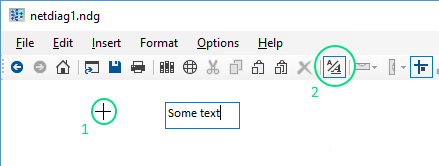
Adding Text To A Diagram
|
Click the Text Mode Button Tip: Double right click the background to toggle the last used mode (Paste, Text, or Link) off and on. |
|
Editing Text
Double click text to start editing it. The Text Mode
button will indicate you are in text mode. Press ESC to finish editing the text, or click the text mode
button on the toolbar.
To delete a Text Box, double click it and then hit backspace. Press
ESC or click the text mode button to exit text mode.
Formatting Text
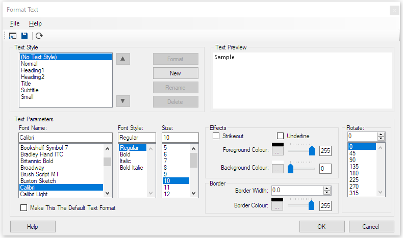
To Format Text, right click text in your
diagram and select Format Text. The Format Text window is now
displayed. From here you can set the Font, Font Size, Colours,
Transparency, Effects and also set the angle of rotation in degrees.
You can also select Format > Text Styles from the main ring menu to
make adjustments to Text Styles.
| Text Style: | Commonly used text formats can be created and named using these settings. Right click text in your diagram and choose Set Text Style to select from defined text styles. Text Styles can be saved to and loaded from file. |
| Make This The Default Text Format: | Sets the default text format used when adding text to a new diagram. |
Moving Text
To move text, hold the left mouse button down on
the text for 1.5s, then drag the text to the new position.
Alternatively hold the SHIFT key
down and drag the
text.
To Rotate Text, hold the SHIFT key down and drag one of the
corners of the text.
Text Types
Text can be set to one of four possible types by right-clicking and choosing "Set Type":
| "Default" | - For standalone text. Enter key adds a new line. Use escape key (or button on toolbar) to submit. |
| "Caption" | - For normal object captions. The enter key or escape key submits (or button on toolbar). Shift-Enter adds a new line. |
| "Address" | - As caption label, but is displayed according to the Show/Hide IP Addresses button on the toolbar. |
| "Flow" | - Caption for flowchart symbols. Enter key adds a new line. Use escape key (or button on toolbar) to submit. |
Adding Float Text To Objects
Information can be displayed when the pointer is held over an
object for a few seconds.
To Add or Edit Float Text, right click the object and select Edit Float
Text.
Enter text into the Float Text entry box and hit escape when complete.
Float Text can also be accessed from the Float text tab in the Object
Properties
form.
Text Properties Toolbar
![]()
The Text Properties Toolbar is optionally displayed
by selecting Options > Text Properties Toolbar. It provides access
to the properties for the most recently clicked text or if no text is selected
it provides access to properties for the current font which is used when
adding new text.
The controls displayed on the toolbar
are covered in the Format Text section above.
Adding Backbones
|
Add horizontal and vertical backbones to your diagram by selecting them from
the Backbones object library. |
|
Resizing And Moving Backbones
To resize a backbone, position the mouse pointer over either
end then hold the left mouse button down to drag the backbone larger or
smaller.
To move a backbone, hold the shift key down whilst dragging the backbone to
a new position.
Customizing Backbone StylesBackbones are Shapes and they can be customised by right clicking and select Format Shape. |
|
Linking An Object To A Backbone
To link an object to a backbone, click on the link
mode button ![]() and then join the backbone to the object.
and then join the backbone to the object.
Grouping and Locking
Objects may be grouped together and then locked in position relative to each other to form composite objects.
The first object you select will become the "parent" object and further
objects selected will be "child" objects.
Select the parent object, followed by the child objects and then select
Format > Group from the ring menu to group the objects together. At this
point, you may still move the objects relative to each other. Copying and
pasting the parent object will copy and paste all of the child objects as
well.
To lock the child objects position relative to the parent object, right
click the child object and select "Lock" from the menu. Now when you move
the child object, the parent and all of its child objects are moved
together. If you resize the parent object all locked child objects are
also proportionally resized and moved.
Right-clicking a parent object and selecting Lock > Group Lock or Group
Unlock locks or unlocks all child objects and labels associated with the
object.
To ungroup objects, select each of the members of the group and
then click Format > Ungroup on the ring menu.
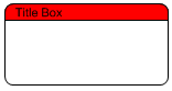
Example using the two shapes created in the Custom Shapes section to form a composite Title Box object:
|
|
Position the two shapes to form a title box. |
Locking objects which are not a member of a group is used to lock the position of the object on the page. This is useful for things like template borders and title blocks which don't normally need to be moved. Objects locked to the page have the following properties:
- They cannot be moved with drag and drop.
- They cannot be selected with CTRL-A or by dragging a band around them.
Anchoring and Locking
Anchoring fixes the position of objects and text relative to one of
the four corners of the page. This is useful when resizing the
page to ensure a title block and border remain fixed to the edge.
Select objects and text to be anchored and then Format > Anchor from the
menu.
Locking objects and text prevents them from being dragged to a
new position (relative to their parent) and also prevents them from
being selected and unselected using CTRL-A. It is useful if the title
block and border are locked. You can then select your diagram using
CTRL-A and reposition it using drag and drop or nudge, without adjusting
the position of the title block and border.
Select objects (link
nodes) and text to be locked and then Format > Lock or right click
objects or text and select Lock.
Rotating Objects and Text
|
Rotate objects and text using any of the following methods:
|
 |
Display or Hide IP Addresses
To Display or Hide IP addresses, toggle the IP Address
Button ![]() on the toolbar.
on the toolbar.
|
 |
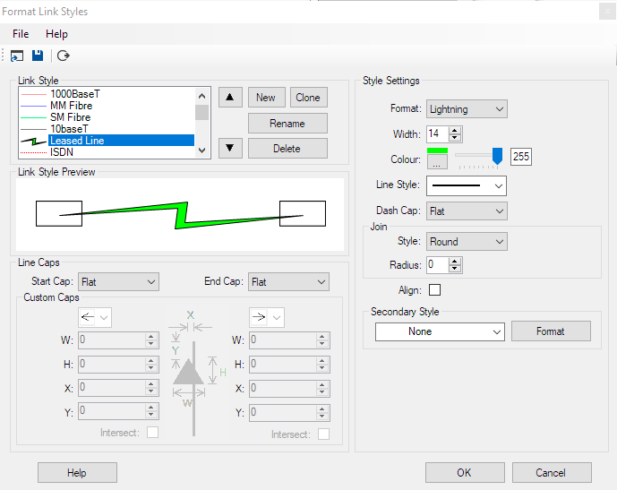
Formatting Link Styles
Select Format > Link Styles on the ring menu or right-click a link and select Format Link style.
|
|
||||||||||||||||||||||||||||||||||||||||||||
The Up and Down Arrow buttons enable you to change the order in which Link Styles are presented. Style Settings
Line Caps
File Menu Options
|

|
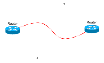 |
Curve2 Link StyleCurve2 Link Style allows you to draw curved Links with any number of
control points. |
 |
Managing Link Styles
Every page in a document contains a set of link
styles. When you access a page in a document the drop down list of link styles on the
toolbar is populated with that page's set of link styles.
From the Format Link Style form you can save the current page's link styles
to a file. On the same menu, "Open" is used to load and replace the
current page's link styles.
A default set of link styles is stored in the linkdefs.nls file. This file
is used to populate the link styles when you start Network Notepad and when
starting a new document and when inserting a new page provided you select
"None/ Blank" when prompted to select a template. If you select any other template, the
page will use the link styles stored in the template file.
You can replace the default link styles by saving link styles to the
linkdefs.nls file (It may be worth making a backup copy of the file
first).
To replace a set of link styles in a template, locate the templates folder
using "File > Open Templates Folder" on the main menu. Open a template file
and then from the Format Link Styles menu load a set of links styles, save the
template file and close the document. See also templates.
Attaching Labels To Links
|
When labels are attached to
links, by default they are rotated automatically to follow the slope of the link. |
 |
How To Attach Labels To A Link
 |
 |
 |
 |
1. Place labels in approximate positions using the text tool. |
2. Select the link first (black/red circle indication at link termination point) then select each of the labels. |
3. Click Format and then Group. The labels are grouped with the link and are automatically rotated to follow the slope of the link segment. Selecting the link now also highlights the related labels. |
4. Finalise label positions using Drag and Drop or nudge. |
Switching Off Label Rotation
Right-click the label and untick "Rotate to follow slope".
Alignment PointsThere are three alignment points on a
link segment, one at each end and one in the centre of the
link segment. The position of a label is relative to the
nearest alignment point when the label was first grouped
with the
link. Detatching A Label from A LinkTo detach a label from a link,
right-click the label and click Ungroup in the context menu. |
 |
Working With Shared Documents
Network Notepad Enterprise Edition includes features which enables multiple users to edit shared documents/ diagrams safely. It solves the problem where a document which is edited simultaneously by more than one user results in changes made by one user being overwritten by another user.
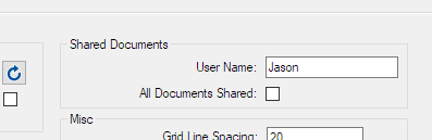
| In the Setup form,
first make sure all users have a unique User Name assigned. (Do not tick/check the "All Documents Shared" checkbox for now. See the Setup Form section for more information about this.) |
 |
|
To make the current document shared, tick the shared document box in the Diagram Properties Form. |
 |
|
| A shared document is initially opened in read-only mode. All edit functions are disabled until the user clicks the Lock File Button. |
 |
|
| A "lock file" is created along side the document file. It stores the name of the user who has locked the file and the time and date the lock was created. |
 |
|
| Other users who have the document open will see the status displayed in the title bar. They are blocked from editing the document until the lock file is released. |
 |
|
| To release the lock click the Lock File button again. The document is automatically saved. | ||
| The status is reflected in the title bar for other users and the refresh button changes colour to red to indicate an update is available. |
 |
|
| Clicking the refresh button reloads
the document. Locking the document automatically refreshes the document first if the diagram has been updated by another user. |
User-Defined Apps
A list of user-defined Apps is presented for execution
when you right click an object. The first 6 of the Apps are also
available using the function buttons on the main toolbar:
![]() .
Variables such as IP address or hostname of the object can be included
in the App definition.
.
Variables such as IP address or hostname of the object can be included
in the App definition.
A set of user-defined Apps is called a
toolset. Multiple toolsets can be configured for use with
different types of equipment and then assigned to the objects in your
diagram from the Object Properties form.
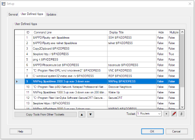
Configuring User-Defined Apps |
|||||||||||||||||||||||||||||||||||||||||||||||||||||||||||||
|
|
|||||||||||||||||||||||||||||||||||||||||||||||||||||||||||||
| Command Line: | This is the command which is executed when the app is
selected. |
| Display Title: | This is the text displayed in the menu. If left blank the Command Line is displayed instead. |
| Hide: | If set to true will minimise the Network Notepad window when the app is run. |
| Multiple: | If true then the tool is run against all selected objects. If false then the tool just runs for the most recently clicked object. |
Variables
The following Network Notepad variables may be included in the Command Line and Display Title definitions:
| $IPADDRESS | Substituted for the most recently clicked
object's IP address. $IPADDRESS is truncated at a "/" character. |
|
| $ADDRESS | Substituted for the most recently clicked
object's IP address (and is not truncated like $IPADDRESS). |
|
| $HOSTNAME | Substituted with the most recently clicked
object's hostname. |
|
| $BROWSE | Invokes the default browser/application. E.g.1. $browse http://$ipaddress..... will open the object's ip address in a web browser window. E.g.2. $browse c:\docs\$hostname.doc..... will try and open for example "router1.doc" in whatever application is configured to handle .doc files. |
|
| $EXPLORE | Invokes an instance of Internet Explorer. E.g. $explore $ipaddress...... to browse the object by ipaddress. |
|
| CopyToClipboard | Copies the resolved definition to the windows
clipboard. |
|
| $FILENAME | Substituted for the current diagram's filename
(.ndg). |
|
| $VAR1,$VAR2 | User variables. These are set in the Object
Properties Form on the Misc Tab and can contain any user-defined
data. Ellipsis buttons are provided to browse for filenames. E.g. $browse $VAR1..... Could be used to open a specific file associated with the object. |
|
| $FieldN | Passes field number N from the object table.
e.g. the CDP user-defined app tool definition includes $field2
to pass the object number which it then uses to construct the
data put on to the clipboard. |
|
| $HWND | Passes the Network Notepad Windows Handle. |
|
| $ADDRLIST | Functionally the same as $ADDRESS, but intended
to pass a list of IP addresses separated by ";" characters. |
|
| $APPDIR | Substituted with the Network Notepad
installation folder. For the Professional Edition it usually returns C:/Program Files(x86)/Network Notepad Professional/ For the Enterprise Edition it usually returns C:/Program Files(x86)/Network Notepad Enterprise/ For Network Notepad Client it usually returns C:/Program Files(x86)/Network Notepad Client/ |
|
| $DOCVAR1 | Per-document user variable which is
configurable in the Diagram Properties form. |
|
| && | Enables multiple apps to be called in one
definition. See the Wake-On-Lan Tool example below. |
Example Command Lines:
- Use SSH to connect to a device using Putty:
"C:\Program Files\putty\putty.exe" -ssh $IPADDRESS
In this example putty.exe has been installed to the Network Notepad program folder:
putty -ssh $IPADDRESS
- Use Putty in telnet mode to connect to a device:
"C:\Program Files\putty\putty.exe" -telnet $IPADDRESS
- Open a web browser session to a device's IP address:
$BROWSE http://$IPADDRESS
- Remote control a device using VNC:
"C:\Program Files\UltraVNC\vncviewer.exe" $IPADDRESS
- Remote Desktop:
C:\windows\system32\mstsc.exe /v:$IPADDRESS
- Open a spreadsheet to access for example asset information for
each device in your diagram:
$BROWSE "F:\Asset Files\$hostname.xlsx"
- NNPing Tool:
NNPing $IPADDRESS 1000 3 up.wav 3 down.wav - Wake-On-Lan Tool:
NNPing $IPADDRESS 1000 3 up.wav 3 down.wav on&&nnwol.exe $VAR1
Where && is used to separate and execute multiple apps.
User variable $VAR1 is configured in the Object Properties form on the Misc Tab and is set to provide
<broadcast IP address> <port> <mac-address>
e.g. 192.168.1.255 9 21-3a-55-37-6e-76
The nnping "on" parameter overrides the usual toggle-on, toggle-off state when calling nnping.
|
 |
Tip: Enclose file pathnames containing spaces with quotation marks as shown in the first three examples above. If you don't do this then Windows cannot distinguish the difference between c:\program files and c:\program.exe for example.
| Copy Tools From Other Toolsets: |
When creating a new toolset you can use this option
to list all tools in all toolset and tick those you wish to copy to the
new toolset. |
| Up/ Down Buttons | Change the order the tools are presented by moving the selected tool up or down in
the list of tools. |
| Toolset: | Network Notepad Professional and Enterprise Editions allow you to define multiple toolsets. You can choose a toolset to use
with an object in the Object Properties form. |
| Naming Toolsets: |
Toolsets can be named by entering text in the Toolset dropdown list in
place of the default numbers. |
| Add Toolset Button
|
If you need more than the default 10 toolsets,
you can add more with this button. |
| Edit Button
|
Toolset definitions are stored in a local tooldefs.txt file. This button enables you to edit the file directly, making it easy to copy, paste and share toolsets. Here is an excerpt from a tooldefs.txt file: |
|
|
|
| When editing the tooldefs.txt file keep the numbers in
brackets in order. That is (toolset number) in the case of the
Toolset statement and (toolset number, tool number) in the case of the
Command, Display,Automin and Multiple statements. When you have finished editing the tooldefs.txt file, save the file and then click the Refresh button in the Setup form to re-read the file contents into Network Notepad.. |
| Refresh Button
|
The refresh button is used to re-read the tooldefs.txt file after editing it outside of Network Notepad. The tooldefs.txt file is written to when you click the OK button. |
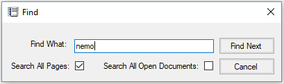
Tip: Network Notepad Files are stored as plain text. Use Windows "Search for Files" to scan through all your diagrams and find what you are looking for.
THE OBJECT PROPERTIES FORM |
Object Properties Form
|
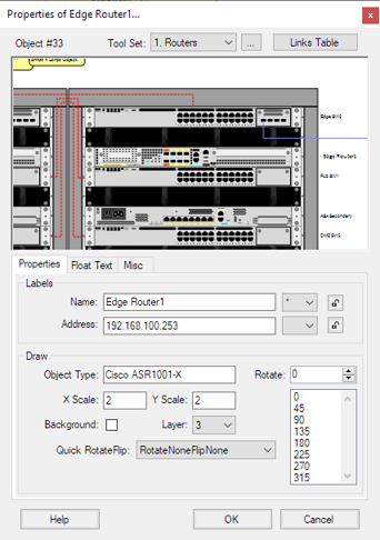 |
| Layer: |
Sets the order which the object is drawn. The backdrop and grid
lines are drawn first followed by objects, labels and links at layer 5 up to layer 0. The "Send to Back" and "Bring to Front" buttons on the main toolbar moves the selected items through the different layers. |
| Background: | Setting an object to background allows links to be drawn on
top of an object rather than connecting to it. (You can also draw a link on top of an object by using the right mouse button instead of the left when forming a join in the link). |
| Quick RotateFlip: | Allows a number of preset rotations and
translations of the object. |
| Rotate: | Specify the objects angle of rotation in degrees, or select from
the list of rotations at 45 degree intervals. You can also use the mouse to drag and rotate. |
| Float Text Tab | |
| Text entered here is displayed when the mouse pointer
hovers over an object. |
|
| Misc Tab | |
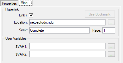
| Hyperlink: |
See Linking Diagrams section below. |
| User Variables: |
User-defined variables $VAR1 and $VAR2 can pass any
text you like to user-defined apps. Ellipsis buttons give the option to browse for filenames. |
Linking Diagrams
| Diagrams may be linked together such that one or more special objects provide a link to other pages or files. To follow a link to another diagram, right click the object and select "Goto next diagram" or double click the object. To configure an object to link to another page or file use the following settings on the Misc Tab in the Object Properties form: |
 |
|
| Link?: | This tick box enables the "Goto next diagram" option when this object is right clicked. | |
| Location: | Filename of next diagram (include .ndg extension). Leave this blank for the current diagram. | |
| Page: |
Optional page to open in the next diagram. |
| Seek: |
Optional text to seek and centre-on when the next diagram is loaded.
|
| Use Bookmark: | Completes the Location, Seek and Page fields with the last bookmarked location (Edit > bookmark). |
|
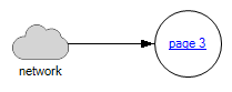
Example We will link an object on page1 to an object on page 3: Go to destination object on page 3. Right-click the object and click "Bookmark Object". Go to the source object on page 1. |
 |
|
Open it's Properties and select the "Misc" Tab. Tick the "Link" box, click "Use Bookmark" and then click OK. You can now right-click the object on page 1 and click "Go To Next Diagram". To create a link back the other way, bookmark the object on page1 and add it to the properties of the object on page 3. |
|
Drag And Drop Method For Linking Diagrams
Another way to create a link to a diagram is to drag and drop the .ndg file you want to link to on to a blank part of the page. This adds an object which provides the link as discussed above.
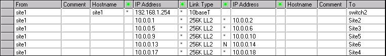
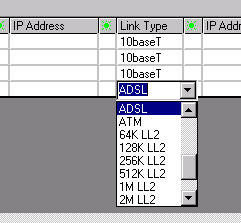
The Links Table
Object Properties Toolbar
The Object Properties Toolbar is optional. It provides quick access
to some of the properties for the most recently clicked object.
Enable the toolbar by selecting Options > Object Properties Toolbar
from the main ring menu.
The controls displayed on the toolbar
are covered in the Object Properties Form section above.
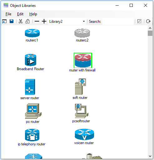
OBJECT LIBRARIES |
|
 |
 graphic in it's place when the document is loaded.
Adding Objects To An Object Library
Drag a .ico, .bmp, .wmf, .gif, .png or .jpg file
on to a blank part of the Object library form.
Right clicking an object allows you to change an
objects default name, filename and X/Y scale.
Use "File","Save Object
Library" to save the updated Object Library file.
It is recommended to leave the default libraries unchanged and
create a new library instead when adding new objects.
Creating A New Object Library
From the Object Library ring menu select File>New to create a new, blank Object Library file. Paste new object images as explained previously and then use File > Save As to save the new Object Library.
Deleting Objects From The Object Library
To delete an object from the current Object Library, select the object followed by "Edit" and "Cut Image from Object Library".
Auto-Hiding The Object Library Form
To auto-hide the Object Library Form whenever an object is selected click File > Auto-hide.
Workgroup Object Libraries
A workgroup Object Library (Folder) may be specified in the main
setup form. Network Notepad will use this library when the shared drive
is available. Otherwise it will use the default local copy.
To set this up initially, copy contents of the local libraries folder to the
shared folder.
Copying An Object Library
You have created your own Object Library, how would you
share it with a colleague?
An Object Library usually consists of an index file (.plf) and
multiple bitmap
files (.bmp,.gif,.png,.jpg), metafiles (.wmf,.emf) and icon files (.ico).
All of the Object Libraries and associated graphic files are stored in a
single object library folder. To make it easy to copy an Object Library and
all of its associated grahics files there is a menu option in the Object
Library window "Copy Object Library". This copies the current library index
file and all the associated graphics files to the Windows clipboard so that
you use the Windows Explorer paste option to copy the files to a new folder.
From there you can zip the library to make it portable.
Update: The latest versions now have a menu option
File > Save Library To .Zip File which creates a .zip file from a
library index file and associated graphics files.
Installing An Object Library
To install an object library which has
been saved to a .zip, from the object libraries window, click File >
Open Object Libraries Folder. Unzip the object library file to this
folder.
CREATING CUSTOM SHAPES |
Shapes are simple graphics which can be customised. There are some
shapes preconfigured in the "Shapes" and "Backbones" Object Libraries.
Select Format > Shape from the main ring menu or right click a shape in
a diagram or Object Library.
Format Shape

| Template Shape: | Is
a list of shapes populated from the current diagram or library. The selected
shape is used as the starting point for further customization. |
|
| Shape Parameters: | Are the settings which control how the shape is
drawn. |
|
| Format: | Choose from a list of basic shapes. |
|
| Width and Height: | Sets the default width and height of the shape. The
graphic can be resized later using the X/Y scale in the object properties
form. |
|
| Corner Radius:/Offset: | Set corner radius for rectangular shapes.
For parallelogram shapes Offset adjusts the offset of two of the sides. |
|
| Antialias: | Select between On,Off and On rotate. |
|
| Colours: | Choose the background colour of the shape. Select a second
colour if gradient fill is to be used. The slider sets the transparency. |
|
| Gradient Fill: | Tick the enable box to enable gradient fill.
X1,Y1,X2,Y2 sets the start and end coordinates of the gradient fill. |
|
| Border: | Set the width >0 for a border to be displayed. The rest of
the parameters here set the colour and dash style for the border. |
|
| Output, Shape Name: | The name of the customized shape to save. It is important to try and keep customized shape names unique. For example, if you created a new shape called "circle" and there is already a different shape in your diagram called "circle" you will not get the desired result when the new shape is added to your diagram (You cannot over-write an existing shape with another shape by giving it the same name but you can modify the existing shape). The ellipsis button may be used to generate a new random shape name. |
|
| Update all: | Selects whether or not to replace
all shapes in the diagram of the type originally clicked with the new shape
if the name of the shape has changed. |
|
| Save to Diagram: | If you selected format shape by right clicking a
shape in a diagram, this option chooses whether that shape is replaced with
the new shape. |
|
| Save To Library: | When defining a new shape you should tick this box to save the new shape to an Object Library. The elipsis button is used to select a different library to save to. |
Example Shapes |
||
 |
Rectangle, Width=200, Height=100,
background set to transparent by setting the colour slider control to
the left. Arc size 20 sets radiused corners. |
|
|
|
Rectangle, Width=200, Height=100. This variant has only the top two corners radiused. |
See Grouping and Locking for information on combining these shapes in to a composite object.
SCRIPT OBJECTS |
"Script Objects" provide a way to construct vector-based
graphics
for use in Network Notepad from plain-text scripts. Some examples
are available in the
scripts library.
Script Syntax
A Script Object consists of the following statements and commands:
1. The Script Statement.
2. Path Statements.
3. Pens and Brushes.
4. Commands.
5. Align Statements.
Format Script Object
Format Script Object provides an environment for creating and modifying Script Objects. Access it from the Format menu or right-click a Script Object in a diagram or the library window.
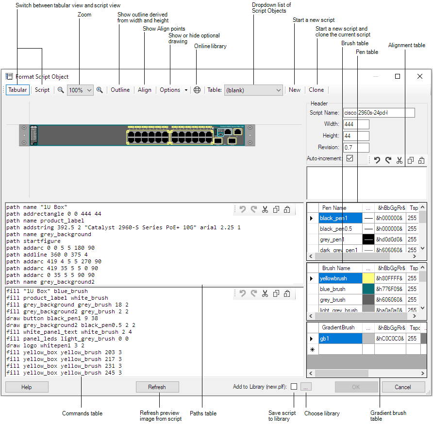
To paste a script in to the editor, switch to script view
(Script button) and paste in to the main panel.
Colour
Pickers for pens and brushes are available in the Tabular view
by clicking the elipsis column (...) in the
respective tables.
&hBbGgRr& specifies the Blue, Green and Red
components of the colour in Hex.
Tspcy is the colour
transparency value from 0 to 255, where 255 is solid colour.
The form is resizable and the panels can also be resized by dragging
the horizontal and vertical bars which divide the panels.
Click the Refresh button to apply changes made in the script panels.
Merging Script Objects
Format > Merge Script Objects enables
mulitple Script Objects to be merged in to a single Script Object. Text can
also be merged.
In the following example an small ethernet hub is built up
from components in the online Script Objects Library and then merged:
1. Add the parent object which will act as a container for the
other components.
I have used Format Script Object to create a
box and given the script a new unique name (this is important).
|
|
script "Netgear FE104" 158 25 0.5 brush blue_brush &h8B4001& 255 path name Box path addrectangle 0 0 158 25 fill "Box" blue_brush |
2. Copy and paste script components from the
online library on to the parent object.
I have added four RJ45
sockets and then using the Text tool added a brand label.
![]()
3. Put the parent box and child components in to a
group.
Select the parent Box first followed by the 4 sockets and
the label, then select Format > Group on the ring menu.
The
objects are now loosely bound together.
![]()
4. Select the group by clicking the parent box
and then select Format > Merge Script Objects.
The parent box and
the 5 child objects are now merged into a single Script Object.
|
|
script "Netgear FE104 Hub" 158 25
0.6 brush blue_brush &h8B4001& 255 brush black_brush &h000000& 255 brush silver_brush &hd0d8dc& 255 brush brush1 &hFFFFFF& 255 path name Box path addrectangle 0 0 158 25 path name rj45down path addlines 2 7 2 9 3.5 9 3.5 10 9 10 9 9 10.5 9 10.5 7 12.5 7 12.5 0 0 0 0 7 path name single_port path addrectangle 0 0 15 12 path name path1 path addstring 0 0 NETGEAR arial 3 1 fill "Box" blue_brush fill single_port silver_brush 111.5 8 fill rj45down black_brush 112.5 19 1 -1 fill single_port silver_brush 66.5 8 fill rj45down black_brush 67.5 19 1 -1 fill single_port silver_brush 81.5 8 fill rj45down black_brush 82.5 19 1 -1 fill single_port silver_brush 96.5 8 fill rj45down black_brush 97.5 19 1 -1 fill path1 brush1 5.25 2.25 |
5. To save the new object to the current local library,
right-click the object and select Format Script Object. Click the
"Save to Library" checkbox and click
OK.
Please email me a copy of your new scripts (or any new components) for
inclusion in the online library!
There are a number of restrictions with the Merge Script Objects feature:
The component objects must not be rotated.
The component objects must use their default x-scale and y-scale settings (That will be 1,2 or 4 depending on the Format > Resolution setting).
Name and Address labels are excluded from a merge.
THE SETUP FORM |
 |
The Setup Form
To access the Setup Form select File > Setup from the main ring menu.
General Settings Tab
| Language: | Select the Language used for Network Notepad. |
|
|
|
This button opens the selected language translation file for editing. |
|
|
|
This button refreshes translations from the language translation file. |
|
| Show index: | To assist with language translations this
temporarily prepends entries with section number and line number to show where
each text entry is located in the language translation file. |
|
| User Name: | Sets the name stored in lock files to show other users who is
editing a shared document. The name must be unique. In
Network Notepad Client this is also used to authenticate a user
connecting to the Network Notepad Server. |
|
| All Documents Shared: | When this option is enabled,
all documents are automatically set as shared
documents which must be locked before they can be edited. For finer control, set
individual documents to be shared in the Document Properties form. |
|
| Windows Date Time Format: | This just displays the Date Time
format currently configured in Windows for reference. This setting will
be removed in a future release. |
|
| Lock Date Time Format: | Leave blank. This setting will be removed in a future release. |
|
| Grid Line Spacing: | Sets the spacing for grid lines when grid lines option is switched on (Options > Grid Lines). |
|
| Default IP Address: | A partial or complete IP Address which will be applied to all new objects added to the diagram. |
|
| Maximum Open Documents: | Sets how many documents can be opened at once. Each open document presents its own tab bar at the bottom of the screen. |
|
| Default Diagram: | Sets the diagram loaded by default if no diagram is specified on the command line. Use the ellipses button to browse for a file or the "Use Current" button to make the current diagram the default diagram. The "None" button clears the default diagram. |
User-Defined Apps Tab
For information on the User-Defined Apps, see User Defined Apps.
Monitoring Tab

Default Node Settings
Sets the default node settings
applied when adding new objects. Node settings are used by add-ons such as
NNMonitor and Network Notepad Client/Server to set what actions to take when a node changes state. Node settings can be changed for individual objects from the "Node" menu when you right-click an object.
| Monitor: | If ticked the node will be pinged by NNMonitor or
Network Notepad Server. If unticked the node will not be monitored. |
| Audible Alert: | If ticked, when a node change of state is confirmed an audible alert is sounded. |
| Log: | If ticked, when a node change of state is confirmed it is recorded in the log file. |
| Email: | If ticked, when a node change of state is confirmed an email alert is sent if emailing has been configured in NNMonitor or Network Notepad Server. |
Overlays
Sets the style and colour used for overlays set by add-ons such as
NNMonitor, NNPing and Network Notepad Client/Server to indicate the up, down or transitioning state of nodes.
Status Panel
Choose the colours and fonts used for each status shown in the Status Panel.
Updates Tab

| Enable Automatic Updates: | Tick to enable automatic updates (default). |
| Update Type: | Select from Automatic, Check and Download, and Check only. |
| Manual Proxy Settings: | Tick to enable automatic updates with manual proxy server settings. |
Client Tab
The Client Tab shows settings specific to Network Notepad Client.

Status
| Flash Time: | When a node state change is confirmed the node flashes for the period of time in seconds set here. |
| Up Sound: | When a node state changes to up, if audible alerts are enabled for the node, this is the wav file played. |
| Down Sound: | When a node state changes to down, if audible alerts are enabled for the node, this is the wav file played. |
Encryption
| Encryption Key: | This is used to encrypt communications between Network Notepad Client and Server and also to encrypt user account data. It must be exactly 32 characters in length (=256 bits) and must match the encryption key configured in Network Notepad Server. Please see documentation here before changing this. |
Misc
| Auto-connect: | When Network Notepad Client loads a document which is configured with the address and port of the Network Notepad Server it will automatically connect to it if this option is ticked. If it is not ticked you must open the Connection Manager window and click Connect instead. | |
| Keepalive: | This setting specifies how ooften Network Notepad Client sends a keepalive message to the server to ensure the server connection is still active. | |
| ConnMgr Log Level: | Specify additional logging in the connection manager window. |
THE DIAGRAM PROPERTIES FORM |
The Diagram Properties Form
The Diagram Properties Form is accessed from the main ring menu File > Edit Diagram Properties.

| Document | These first three settings apply to the
whole document. |
| Shared Document: | See Working with shared documents. |
| $DOCVAR1: | This is a per-document user variable which can be
passed to user-defined apps. |
| Auto-run app: | A customer requested an option to auto-start
NNMonitor when a document is loaded and this setting is where
this is configured. It can be used to launch any user-defined
app, but with the restriction that it will only run if it
exactly matches the command line of a user-defined app. If it is
not an exact match an error message is displayed. |
| Page | The following settings apply to the
current page. |
| Diagram Name,
Notes1,Notes2: |
These are text fields stored in the diagram. |
| Settings | |
| Resolution: | Select from Draft, Fine and Superfine. Fine uses a bitmap which is twice as big as Draft and Superfine uses a bitmap which is twice as big as Fine. |
| Page Width and Height: | Specify the size of the page in pixels. See also Printing. |
| Lock button: | Locks the page width and height so that the
page cannot be resized with the mouse. |
| Backdrop: | Specify an image file for the Backdrop of the diagram. |
| Colours | |
| Forground Colour: and Background Colour: |
Sets the colours used for Object Name and IP Labels. |
| Link Text Colour: | Selects the colour for text used to highlight
objects which link to another diagram. |
| Float Text Foreground and Float Text Background Colours: |
Sets the colours used for Float Text. |
| Make These The Default: | Use the settings specified for this page as the default settings for new diagrams. |
TEMPLATES |
Diagram Templates
When you start a new drawing or add a new page to an existing document,
you are prompted to select from a list of templates. A diagram template is
simply a minimal diagram containing defaults you commonly use in new
diagrams. It
sets the page width, height and orientation and can set text styles, link
styles and some default drawing, for example a title block, border and logo.
Creating Diagram Templates
To create new diagram template, set up a new single page document with
the desired settings and default drawing as mentioned above and then save it
to the templates folder using File > Save to Templates.
NETWORK NOTEPAD CLIENT/ SERVER |
|
|
Network Notepad Client/ Server
How It Works
 |
1. Network Notepad Server can be run as a standalone
executable file or as a Windows service to provide the following functions:
It reads a single diagram file (.ndg) and continuously monitors the nodes in
the diagram using Ping.
It accepts connections from and authenticates Network Notepad Clients and it provides node status
information to the clients.
It can send out emails when it detects a node has changed state.
It accepts NNServerConsole connections for remote administration of the
server.
2. The monitored diagram is stored on a drive which is accessible to both the Network Notepad Server and Network Notepad Clients. This can be on the same server as Network Notepad Server or on a separate File Share or NAS (or on the Network Notepad Client if everything is on one PC).
3. A Network Notepad Client opens the diagram file and the diagram is displayed. The client then looks at $DOCVAR1 in the diagram properties to see if it provides an IP Address and Port for a Network Notepad Server. The format for $DOCVAR1 to supply Network Notepad Server details is "-socket <server ip address>:<server port>".
4. If the diagram provides the Server IP Address and Port, the Network Notepad Client connects to the server and is authenticated if authentication is enabled.
5. The Network Notepad Server provides node status
information to the client and the client displays this as
overlays in the diagram and in tabular format in the Status Panel form. The server
continues to send node updates to connected
clients whenever it detects a change in state for as long as the clients
remain connected.
6. The Network Notepad Server can send out email alerts when a node changes
state.
7. NNServerConsole is a small app deployed with the Network Notepad Client
software for remotely
administering the server. It displays a real-time view of events on the server and
provides administrative functions such as adding user accounts.
Network Notepad Server Requirements
Network Notepad Server (NNServer) can be run on a
Windows PC, a Windows server, or it can be run on a Linux box using Mono. An
article on building a Raspberry-Pi-based Network Notepad Server will be
published later.
NNServer targets .Net framework 4.7.2, so should work with Windows 7 Service
Pack 1 and later versions of Windows.
A
single NNServer instance is designed to monitor the nodes in a single .ndg
diagram file only. The .ndg file can be
stored on a separate file server or NAS, the NNServer can be the file server,
or the .ndg file can be stored on a client PC if everything is run on a
single PC. If running on a raspberry Pi using Mono, Samba can be used to
make it the file server also.
Installing Network Notepad Server
To install Network Notepad Server, create a folder (e.g. C:\nnserver) and
unzip the contents of the .zip file to it.
The .zip file has
the following contents:
| nnserver.exe | - Command line executable version of Network Notepad Server. | |
| nnserversvc.eve | - Windows Service version of Network Notepad Server. | |
| example nnserver.ini | - Template nnserver.ini configuration text file. | |
| Network Notepad Server License Agreement.txt | - License information for Network Notepad Server. | |
| Mailkit and MimeKit License Information.txt | - License information for the libraries used to send emails from Network Notepad Server. | |
| installservice.bat | - Batch file to install Windows service. | |
| uninstallservice.bat | - Batch file to uninstall Windows service. |
It is recommended to initially build and test your configuration using the command line executable version of Network Notepad Server (nnserver.exe) as it is easier to troubleshoot. When it is working ok you have the option to install and run the Windows Service version (nnserversvc.exe).
Setting Up Network Notepad Client For Connecting To The Server
|
Enter a User Name in the field provided
in the Setup form. This indentifies the user when locking a diagram file (as
with Enterprise Edition) and now it also identifies the user when connecting
to a Network Notepad Server.
Also highlighed is the Lock Date Time Format. The server and all of the clients must use the same date time format when writing lock files. The date time format for the server can be set in the nnserver.ini file. Note, in the latest versions of the server and client the default Lock Date Time Format is independent of the Windows Date Time Format, so it is unlikely these settings will need to be changed. The option to change the Lock Date Time Format will probably be removed in a future release. |
 |
Preparing A Diagram (.ndg)
1. The diagram to be monitored must be saved to a location which is accessable by both the Server and the Clients. This could be a shared folder on the Network Notepad Server itself, on a separate file server or NAS, or even on the client if the client and server are all on one PC.
|
2. In the Diagram Properties, it works best if the "Shared Document" option
is ticked. In Network Notepad Enterprise Edition the "Shared Document"
option
is used to manage multiple users attempting to modify a diagram at the same
time. With a shared document you have to
click the Lock button on the toolbar before you can make changes to a diagram
and click the Lock button again when you have finished making changes.
Network Notepad Client uses this unlock event to send a refresh signal to the server that the
diagram has been updated and to reload it and handle any
changes. |
 |
3. In the Diagram Properties $DOCVAR1 field specify the IP Address and TCP port of the Network Notepad Server.
When the diagram is loaded by the server this setting informs it what TCP
port to listen on for client connectons and when the client loads the
diagram it populates the Server address and TCP port settings for the
connection and it initiates the connection process.
In this example
the Network Notepad Server is at IP address 192.168.1.100 and will listen on TCP port 9998 for Client connections:
-socket 192.168.1.100:9998
Note. By default nnserver will listen for connections from the server administration tool NNServerConsole on the TCP port which follows the client TCP port. In this case it will listen on port 9999 for nnserverconsole connections.
4. It is helpful if the diagram contains a graphic/object for the Network
Notepad Server in order to right-click it and launch a user-defined tool
which opens
nnserverconsole (see Setting Up
NNServerConsole section below).
5. Objects in the diagram must have a valid, pingable addresses in order to
be monitored. A valid
address is an IPv4 IP Address, an IPv4 IPAddress followed by a "/" character
(e.g. "192.168.1.1/24") or a DNS name.
Minimal Setup And First Time Run
| On the Network Notepad Server, copy or rename the
"example nnserver.ini" file to nnserver.ini. The settings in this file are covered later. The default settings in the file will be sufficient to get things running. Start NNServer from a command prompt like this
nnserver.exe –file <.ndg file> In Network Notepad Client, open the diagram on the
shared drive. |
 |
Stopping the Command Line Network Notepad Server
To stop the command line Network Notepad Server press CTRL-C.
The Connection Manager Window
| The Connection Manager Window is
displayed when
connecting to or disconnecting from a Network Notepad Server. To open the
Connection Manager window click the button on the toolbar:
|
 |
The Status Panel
| The Status Panel provides a tabular view of
the nodes being monitored and a log of status changes received from the
server. Access it from the View menu. Note. A limitation of the log window is it is cleared when it reaches 30000 entries. |
 |
 |
Setting Up NNServerConsole
NNServerConsole.exe is the remote administration console for Network Notepad Server. It is included with the Network Notepad Client installation and can be launched from a user-defined tool in Network Notepad (The diagram must contain an icon/object for the Nework Notepad Server). Configure a user defined tool like this:
Command Line: nnserverconsole.exe
-consocket
$IPADDRESS:9999
Display Title: NNServerConsole@$IPADDRESS
Connecting To A Network Notepad Server Using NNServerConsole
| Right-click the Network Notepad Server icon in your
diagram and choose the NNServerConsole user-defined tool which was
configured in the previous section. You will be prompted for a password. The default password is "password". The first time you login, you will be prompted to choose a new password for console access. Note there are two tabs available. The Log tab displays server activity. The Terminal tab shows results for commands entered. To see a list of commands available, enter "?" or "help" in the command window: debug [<address>|none] - Debug node help,? - This help page lock - View lockfile details loglevel [n|+n|-n] - View or set the loglevel logout - Logout log - Switch to log tab memory - Show nnserver instantaneous memory usage meminterval [n] - View or set memstats collection interval in minutes memstats - View nnserver memory usage statistics password ["]<user id>["] <password> [change] ping <address> - Ping from NNServer reset email - Reset email counts and startup email count statistics - Show node statistics status - Show status information term - Switch to terminal tab test email - Send test email useradd ["]<user id>["] <password> [change] userdel ["]<user id>["] users - Display list of user accounts version - show NNServer version who - Who's connected |
 |
When you enter a command the display tab
automatically switches to the Terminal tab to
display the result. If you need to return to the Log view, click the Log
tab or type "log".
The "loglevel" command is worth mentioning at this point as it controls what information is logged by the server and is helpful
during setup and troubleshooting to see the server activity. Enter
"loglevel" to see the current setting.
Enter "loglevel 2047" to log all information (switch back to the
log tab to see the result).
Enter "loglevel 0" to minimize the information logged.
You can use loglevel +n or -n to set or clear individual loglevel
bits.
e.g. To add loglevel bit 16 and view timer logging, enter "loglevel
+16".
A full NNServerConsole command
reference is provided below.
Encryption Key
The encryption key is used for two functions:
1. To encrypt data sent between the Network Notepad Clients and the Network
Notepad Server.
2. To encrypt user account data stored on the server.
The encryption key on the server must match the encryption key on the
clients.
The encryption key must be exactly 32 characters in length (=256 bits).
To set the encryption key in the Server, edit the nnserver.ini file and
change the "key" setting.
To set the encryption key in Network Notepad Client, go to File > Setup >
Client tab.
NNServerConsole uses the encryption key configured in Network Notepad
Client.
If you change the encryption key after the console
password has been changed or other user accounts have been added you must
delete and recreate the "passwd" file.
The procedure is as follows:
1. Delete the "passwd" file.
2. Login using NNServerConsole with the default password and set a new
console password when prompted.
3. If you have added any other user accounts, these must be added again
using the useradd command,
see below.
Authentication
To authenticate client connections to Network
Notepad Server, set the "authenticate" setting in the nnserver.ini file.
The default setting is "authenticate console". Change it to "authenticate
all". Save the file and restart NNServer.
The next step is to add user accounts on to the server.
User account information is stored in a file determined by the
"passwordfile" setting in the nnserver.ini file. The default file is
"passwd" as shown in this extract from nnserver.ini:
#
# Set the file used to store user account information on the server. This
file is created when you use the useradd command in the NNServer Console
app.
#
passwordfile passwd
Note: The passwd file does not exist until you set a new NNServerConsole
password or add user accounts.
Adding User Accounts
When you login in to NNServer with NNServerConsole
and chang the default password it will create the "passwd" file and save
the new console credentials in it.
(This is equivalent to running this command: useradd console <password>)
Add user accounts for Network Notepad clients. The userid must match the User Name
configured in the Setup form for each client.
useradd ["]<user id>["] <password> [change]
e.g.
useradd Jason secret
Quotation marks are required around the userid if the userid contains one
or more space characters.
When the optional "change" parameter is included the user is prompted to set
a new password next time they log in.
Changing A Password
A user's password can be changed only after the the
user has been added using the useradd command. Use the password command to
change a user's password:
password ["]<user id>["] <new password> [change]
e.g.
password Jason secret
Quotation marks are required around the userid if the
userid contains one
or more space characters.
When the optional change parameter is included the user is prompted to set a
new password next time they log in.
Viewing User Accounts
To see a list of user accounts which are configured, enter the "users" command:
users
console ********
jason ********
Configuring Network Notepad Server To Send Email Alerts
Network Notepad Server can send email alerts when a
node changes state and it can also be configured to send an email each time
the server process is restarted.
The server requires access to a SMTP server for this to work.
The following extract from the nnserver.ini file shows the
parameters used to setup email alerts:
#
# Email Configuration. NNServer will send email notifications of status
changes when the following variables are set up.
#
emailclient mailkit
emailserver smtp.example.com
emailport 587
emailusername my_email_username
emailpassword my_email_password
emailoptions starttls
emailfrom support@mydomain.com
emailto everyone@mydomain.com
#
# Set a per-node email limit for the number of emails which can be sent in
the per-node email limit time period.
#
emaillimit 10
#
# Set the per-node email limit time period in minutes.
#
emaillimitperiod 60
#
#
# Send an email when NNServer starts or restarts
#
sendstartupemail
#
# Set a maximum number of start up emails per day.
#
maxstartupemails 20
Notes:
| emailclient mailkit | This sets the library used to send emails. The choices are "mailkit" or "smtpclient". mailkit is the recommended setting for smtp servers. |
| emailoptions starttls | This sets sets some security settings associated with the library used to send emails. The choices as "starttls" for mailkit and "sslonconnect" for the smtpclient library. |
| emaillimit 10 | A continuously flapping node could potentially result in a lot of emails being generated, so this setting sets a per-node limit for the number of emails which can be sent in the time period specified below. |
| emaillimitperiod 60 | Sets a per-node time limit period of 60 minutes. The example sets a limit of 10 emails per node in a 60 minute period. |
| sendstartupemail | Unhash this line to send an email whenever the Network Notepad Server process starts. |
| maxstartupemails 20 | Unhash this line to set a limit of sending no more than 20 startup emails per day. |
The NNServerConsole command "reset email" can be used to clear any email limits which have been reached and resume sending emails.
Testing Email Settings
You can send a test email using the NNServerConsole "test email" command:
test email
The Log window will show progress like this:
12/9/2023 1:53:06 PM: SendEmail() connecting to
smtp.example.com port 587 using StartTls
12/9/2023 1:53:06 PM: SendEmail() authenticating with username
support@example.com
12/9/2023 1:53:06 PM: Test email sent to jason@networknotepad.com ok.
Network Notepad Node Monitoring Settings
You can set node monitoring settings for each object
in a diagram by right-clicking an object and selecting the Node menu. The
following options are displayed:
| Monitor | Enable or Disable monitoring the node. |
| Audible Alert | Enable or Disable an audible alert when the node changes state. |
| Log | Enable or Disable whether node state changes are logged for this node. |
| Enable or Disable whether an email is sent when the node changes state. |
After changing a setting, save the diagram by
releasing the diagram lock (Click the Lock button). This will send a signal
to the Network Notepad Server that the diagram has changed.
The default settings for node monitoring when adding new nodes to a diagram
can be set in the Setup form, Monitoring Tab.
Ping Parameters
The following parameters in the nnserver.ini file
set how Network Notepad Server pings nodes. Note all timings are approximate:
| PingInterval 20 | Set the time between ping cycles to 20 seconds. |
| FastPingInterval 5 | Set the time between ping cycles when confirming a state change to 5 seconds. For accurate timing, ideally the fastpinginterval
time should divide evenly in to the
pinginterval time. Pings are also despatched evenly across all
fastpingintervals. FastpingInterval must not be less than the timeout below. |
| DownRetries 3 | The server will ping a node 3 times to confirm the node is down. |
| UpRetries 3 | The server will ping a node 3 times to confirm the node is up. |
| Timeout 2000 | Set the timeout for an individual ping to 2 seconds. |
| PingDelay 10 | Adds a 10ms delay between despatching each individual ping. This may be required when large numbers of nodes are monitored to help avoid heavy bursts of ping traffic on the network. |
Ping Timing Example
If you have 40 nodes in a diagram, using the
parameters above gives 4 fastpingintervals per pinginterval (20 divided by
5), therefore 10 nodes will be pinged during each fastpinginterval + any
retries outstanding from previous fastpingintervals.
Additional fastpingintervals may be added to a cycle until all outstanding
retries are completed before moving on to the next ping cycle.
With a high number of nodes and short ping interval times, or if
an outage causes a lot of ping retries, it is possible to run out of time to
send all of the pings. In this situation a message like this may be logged:
Ping interval delayed. The previous interval is still running!
This message can be ignored if it rarely occurs, but if it is occuring
often you should increase the PingInterval and FastPingInterval times to
avoid it. The PingDelay setting also affects how long it takes to complete a
ping cycle and may also need to be adjusted.
DNS Parameters
The following parameters in the nnserver.ini file set how Network Notepad Server does DNS name resolution:
| DnsInterval 600 | Where node addresses use DNS names as opposed IP addresses, this parameter sets the frequency for resolving the DNS names (looking up the IP addresses). The example does DNS lookups every 600 seconds (10 minutes). |
| DnsIntervalUnresolved 120 | This sets the frequency for resolving currently unresolved DNS names. This example retries looking up unresolved DNS names every 120 seconds (2 minutes). |
LogFile
Network Notepad Server can log to a file. Unhash the
logfile entry in nnserver.ini and specify a filename as shown here:
#Enable logging to a file and specify log filename here
#
logfile nnserver.log
Log files are rolled over at the start of each day and the previous day's
log file is renamed to include the date. It is a good idea to
create a separate folder for logs (Make sure the folder exists). In this
example the entry in nnserver.ini specifies to write logfiles to a logs
folder in the nnserver installation folder:
#Enable logging to a file and specify log filename here
#
logfile C:\nnserver\logs\nnserver.log
An absolute path name for the logfile is recommended when configuring the Windows Service version of NNServer.
Installing Windows Service
(1). Unblock the nnserverservice.exe file
| nnserversvc.exe is the Windows Service executable
file. You may need to "unblock" this file before it can be installed. Right-click the file and open it's properties. Tick "unblock" and click OK. |
 |
(2). Configure the nnserver.ini file
It is not easy to set command line parameters
with a Windows service, so the “-file” command line switch used previously
has an alternative in the nnserver.ini file.
This extract from nnserver.ini shows the default settings:
#
# The following setting is used in place of the -file command line switch
with the Network Notepad Server Windows Service (nnserversvc.exe).
#
# Specify the .ndg file to load and monitor. Use UNC filename rather than
mapped drive letters.
#file "\\192.168.1.100\nas\example network.ndg"
Remove the '#' at the start of the line and set the
filename for the .ndg file.
Use the
UNC pathname of the file (\\server\path\file) when specifying the file. Do
not use mapped drive letters.
e.g.
#
# The following setting is used in place of the -file command line switch
with the Network Notepad Server Windows Service (nnserversvc.exe).
#
# Specify the .ndg file to load and monitor. Use UNC filename rather than
mapped drive letters.
file "\\zen\share\Diagram.ndg"
3. Install the Service as Administator
To install nnserversvc.exe as a service you need to use the
Windows installer tool "InstallUtil.exe". It is usually located in the .Net
folder on a Windows System:
C:\Windows\Microsoft.Net\Framework64\v<version>\Installutil.exe
e.g.
At a Command Prompt run as Administrator, enter the
following command:
C:\Windows\Microsoft.NET\Framework64\v4.0.30319\InstallUtil.exe
"C:\nnserver\nnserversvc.exe"
Alternatively use the installservice.bat provided. Note: This script assumes the
location of the InstallUtil.exe file is as above.
Right-click the installservice.bat file and choose Run as administrator.

(For info, if you need to uninstall the Network
Notepad Server service use the -u flag e.g. C:\Windows\Microsoft.NET\Framework64\v4.0.30319\InstallUtil.exe -u
"C:\nnserver\nnserversvc.exe" or right-click the uninstallservice.bat file
and choose Run as administrator
In Windows Services, use Action > Refresh to see the Network Notepad Server service listed:

4. Configure Service Log On

NNServerConsole Commands Reference
| debug <address> | Shows when the server is pinging the target address. > debug 192.168.1.254 5/9/2024 8:41:43 AM: Debugging node 192.168.1.254 Switch to the log window to view the results: 5/9/2024 8:41:49 AM: Ping result for 192.168.1.254 (192.168.1.254) interval 1 seq 54867 (54866) Reply address 192.168.1.254 up 0ms To turn off debugging enter "debug none" > debug none 13/05/2024 20:06:45: Debugging switched off |
| help, ? | Display help page |
| lock | View lockfile details. > lock LockFile: /nn/demo network.lck Lockee: Jason Green Lock time: 6/21/2024 11:01:05 AM UTC Instance: C Locked: True |
| loglevel [n|+n|-n] | Loglevel with no parameters displays the current
loglevel. Each bit value of the loglevel controls what is logged by
nnserver e.g. > loglevel loglevel is set to 19 ✓ bit 1 - General debug ✓ bit 2 - Keepalives bit 4 - Incoming messages from clients bit 8 - Outgoing messages to client ✓ bit 16 - Timer bit 32 - Diagram refresh bit 64 - DNS bit 128 - Ping Exceptions bit 256 - Ping starts failing bit 512 - Ping starts succeeding bit 1024 - Locking Loglevel [n] - Changes the loglevel e.g. > loglevel 2047 loglevel is set to 2047 ✓ bit 1 - General debug ✓ bit 2 - Keepalives ✓ bit 4 - Incoming messages from clients ✓ bit 8 - Outgoing messages to client ✓ bit 16 - Timer ✓ bit 32 - Diagram refresh ✓ bit 64 - DNS ✓ bit 128 - Ping Exceptions ✓ bit 256 - Ping starts failing ✓ bit 512 - Ping starts succeeding ✓ bit 1024 - Locking Loglevel [+n|-n] - sets (+n) or clears (-n) bits from the current loglevel value e.g. >loglevel -768 loglevel is set to 1279 ✓ bit 1 - General debug ✓ bit 2 - Keepalives ✓ bit 4 - Incoming messages from clients ✓ bit 8 - Outgoing messages to client ✓ bit 16 - Timer ✓ bit 32 - Diagram refresh ✓ bit 64 - DNS ✓ bit 128 - Ping Exceptions bit 256 - Ping starts failing bit 512 - Ping starts succeeding ✓ bit 1024 - Locking |
| logout | Logout and disconnect nnserver console session |
| log | Switch to the log tab in NNServerConsole. See also term. |
| memory | Displays a snapshot of the memory usage for NNServer. > memory Private Memory(MB), Virtual Memory(MB), Working Set(MB), Paged Memory(MB), Paged System Memory(MB), Non-Paged System Memory(MB) 22.93, 211.73, 24.11, 22.93, 0.29, 0.03 |
| meminterval [n] | View or set the time interval in minutes for collecting
memory usage stats for the memstats command. > meminterval meminterval= 5 (minutes) |
| memstats | Display memory usage data collected since NNServer was
started at intervals set by the meminterval command. The csv data can be
imported to Excel, for example, using the Text Import Wizard (select
the data and press CTRL-C to copy it). > memstats Date,Time,Private Memory(MB), Virtual Memory(MB), Working Set(MB), Paged Memory(MB), Paged System Memory(MB), Non-Paged System Memory(MB) 13/05/2024, 19:42:59, 14.18, 173.72, 22.74, 14.18, 0.26, 0.02 13/05/2024, 19:47:59, 19.95, 204.18, 32.77, 19.95, 0.28, 0.03 13/05/2024, 19:52:59, 21.85, 206.8, 34.62, 21.85, 0.29, 0.03 13/05/2024, 19:57:59, 22.4, 208.32, 34.88, 22.4, 0.29, 0.03 13/05/2024, 20:02:59, 22.41, 205.7, 34.61, 22.41, 0.29, 0.03 13/05/2024, 20:07:59, 22.16, 207.01, 31.04, 22.16, 0.29, 0.03 13/05/2024, 20:12:59, 23.45, 210.42, 31.05, 23.45, 0.29, 0.03 Memory usage data is stored in a ring buffer which is sized to collect 24 hours of stats at the default 5 minute meminterval. Increasing the meminterval by 5x to 25minutes, the ring buffer will hold memory usage data for 5 days, etc. |
| password ["]<user id>["] <password> [change] | Change the password for an existing user. Quotation
marks must be included if the user id contains one or more space
characters. If the optional change parameter is included the user will
be prompted to enter a new password next time they login. See also
useradd command. > password jason secret change Password changed for user jason and they will be requested to change their password at next login |
| ping <address> |
Initiate a ping from nnserver and display the result. > ping 192.168.1.254 Ping reply from 192.168.1.254 up 1ms Ping reply from 192.168.1.254 up 1ms Ping reply from 192.168.1.254 up 1ms Ping reply from 192.168.1.254 up 1ms Ping reply from 192.168.1.254 up 1ms |
| reset email | If the maximum number of emails sent for a node is
reached, further emails for the current time period are disabled. The reset
email command clears the email counts for all nodes and resumes sending
emails. It also clears the email count for the nnserver startup emails.
> reset email Email counts have been reset |
| statistics | Display statistics collected for nodes in csv format.
The csv data can be imported to Excel for example using the Text Import
Wizard (Highlight the data and press CTRL-C to copy it). name,key,seq,success,fail,confirm_up,confirm_down,exceptions,lock,bad_lock_count, .resolved_address,.newstate,.status Edge SW2,192.168.1.81,90208,0,90208,0,0,0,1,0,192.168.1.81,11010,TimedOut Pub SW2,192.168.1.65,90209,90005,204,3,251,0,0,0,192.168.1.65,0,Success Old SW1,192.168.2.104,90208,0,90208,0,0,0,1,0,192.168.2.104,11010,TimedOut DMZ SW1,192.168.1.142,90209,90209,0,0,6,0,0,0,192.168.1.142,0,Success DMZ SW2,192.168.1.67,90209,90209,0,0,229,0,0,0,192.168.1.67,0,Success ... Field Descriptions name - node name. key - node address. seq - This is the sequence number for the current ping to the node. success - This is a count of successful pings to the node. fail - This is a count of failed pings to the node. confirm_up - This is a count of up retries when pinging a node. confirm_down - This a count of down retries when pinging a node. exceptions - Errors executing the ping to a node. lock - A value 1 indicates the node is currently locked for a ping and value 0 shows the node is not locked. bad_lock_count - This is a count of how many times a lock was already in place when attempting to lock a node. A non-zero value here could indicated the timing values set in the nnserver.ini file are too fast. .resolved_address - Where a DNS address is used for the node address this field shows the resolved address. .newstate - A numeric value representing the most recent state of the node. .status - Text description of the most recent state of the node. |
| status | Display status information for NNServer. > status Network Notepad Server version 1.0.37 rev109 beta Filename=D:\Client Features Diagram.ndg PingInterval=12s FastPingInterval=3s PingDelay=1ms Monitoring 59 nodes 4 FastPingIntervals per PingInterval Timeout=2000ms UpRetries=3 DownRetries=3 DnsLookupAllInterval=600s DnsLookupUnresolvedInterval=120s MemInterval=25m Authenticate all MasterTimer.enabled=True LogFileErrors=0 TotalSent=5068792 TotalResults=5068792 |
| term | Switch to the terminal tab in NNServerConsole. See also
log. |
| test email | Send a test email from NNServer. |
| useradd ["]<user id>["] <password> [change] | Add a user account to NNServer. Quotation marks must
be included if the user id contains one or more space characters. If the
optional change parameter is included the user will be prompted to enter
a new password next time they login. > useradd Joe secret change User Joe added successfully. |
| userdel ["]<user id>["] | Remove a user account from NNServer. Quotation marks
must be included if the user id contains one or more space characters. > userdel joe User joe deleted. |
| users | Display a list of user accounts on NNServer. > users surface ******** jason ******** console ******** |
| version | Display the NNServer software version. > version Network Notepad Server version 1.0.37 rev109 beta |
| who | Display a list of users currently connected to
NNServer. > who 2 users connected: console 192.168.1.146:60555 Jason 192.168.1.146:60543 |
Status Panel (Standalone Client)
A Status Panel app is included with Network Notepad
Client. It is used to display a status panel similar to the one built in to
Network Notepad client, but it runs as a standlone app.
You will find it on the Windows Start Menu under Network Notepad Client.
Making A Manual Connection To NNServer
Click the Setup button and enter the account
username which will be used to connect to the NNServer.
Click the Connection Manager button to open the
Connection Manager.
Enter the server ip address and port of the Network Notepad Server and click
Connect.
 |
 |
Command Line Arguments
The Status Panel app supports the following command line arguments
| -socket <address>:<port> | Specify the IP address and port of the NNServer. |
| -username <user-id> | Specify a username to use when connecting to NNServer. |
| -inifile <file> | Read/write settings from/to a .ini file. This is useful if you want to
run more than one instance of the Status Panel and use different settings
for each instance. A template_statuspanel.ini file is included with the
installation. If you don't specify a .ini file, settings are saved in the Registry. |
MISCELLANEOUS |
Adding A Backdrop Image
Drag and drop a bitmap file (.bmp, .png, .gif or .jpg) on to the page
to use as a backdrop image for your diagram.
In the Diagram Properties form, you may also specify a filename for a
backdrop bitmap, and you can select whether to stretch, centre or tile
the image.
Export To Bitmap Graphics File
To export a diagram as a bitmap file, from the ring menu, select File and then Export To Bitmap Graphics File. Enter a suitable filename when prompted. The following bitmap file types can be selected from drop-down list: .bmp, .gif and .png.
Export To A PDF File
To export a Network Notepad diagram or document to a
searchable PDF file:
File > Export To PDF > Export
Page or Export Document
Setting A Default Diagram
You may configure a default diagram to be displayed when Network Notepad is run. The default diagram is configured in the Setup Form.
Working with CSV files
Network Notepad can save to and load from .csv files which means you
can use a spreadsheet to view and edit diagram files.
In the File
> SaveAs and File > Open dialogs select .CSV file in the type
dropdown list.
Import CSV Data
This feature lets you import a list of Objects from CSV data. Open the form from the menu option File > Import CSV Data.
Note: For cultures which use "," as a decimal separator character use ";" as the delimiter.
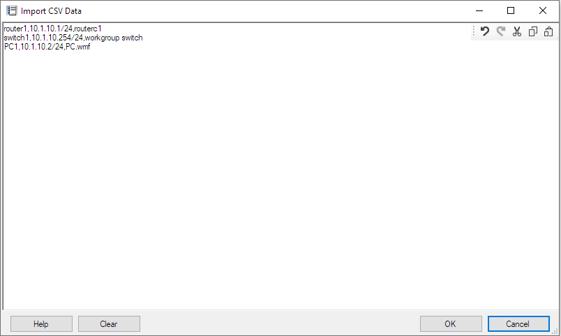
Paste a list of objects in the form in the following format:
Name, Address, Object Type
Example:
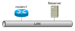
router1,10.1.10.1/24,routerc1
switch1,10.1.10.254/24,workgroup switch
PC1,10.1.10.2/24,pc.wmf
When you click the OK button, Network Notepad switches to paste mode and shows the outlines of the objects to be pasted
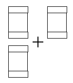
Paste the objects to complete the operation.
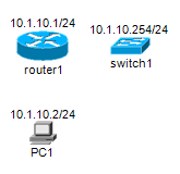
Transfer License To Another PC
When a licensed PC is to be replaced, the Network Notepad license can be transferred to the replacement PC using the procedure shown below. There are a couple of points to be aware of when doing this:
-
Use this procedure only when a complete PC is being replaced. If you are
not replacing a complete PC, such as when upgrading a CPU chip,
replacing a motherboard or replacing a PC but keeping the old hard disk
drive, do not use this procedure. Contact
Support
instead.
-
It is a one-way procedure. You cannot transfer a
license back to the original PC. It is possible to reactivate the
license on the original PC but only with assistance from
Support.
-
As soon as you proceed with the transfer, Network
Notepad will no longer be licensed and will not function the next time
you try to open it.
-
Web browser access to the Internet is required to
create the replacement license file.
|
1. On the PC which is to
be replaced, |
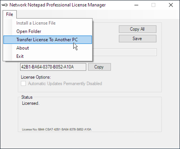 |
|
2. Click OK at the first confirmation dialog. |
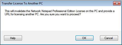 |
|
3. Tick the "I agree" box and click OK at the second confirmation dialog. |
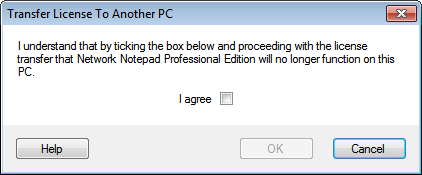 |
|
4. Copy the URL displayed to a PC with Internet access and browse to the URL (If you happen to close the dialog at this point, the URL will be displayed again next time you open the License Manager). |
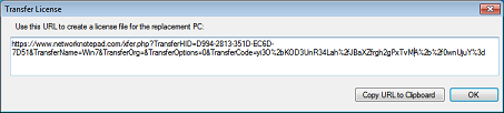 |
|
5. Fill out the online form and enter the Hardware-ID from the new PC (Run the License Manager on the new PC to display its Hardware-ID) and click Next. |
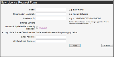 |
|
6. Confirm the details on the next page. |
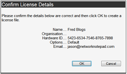 |
|
7. Download the new PC's license file. A copy is also sent to the email address entered in to the form previously. |
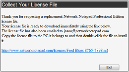 |
|
8. Copy the license file to the new PC and double-click the file to install it or use the Network Notepad License Manager menu option File > Install a License File. |