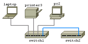
Keyboard and Mouse Controls
|
|||||||||||||||||||||||||||||||||||||||||||||||||||||||||||||||||||||||||||||||||||||||||||||||||||||||||||||||||||||||||||||||||||||||||||||||||||||||||||||||||||||||||||||||||||||||||||||||||||||||||||||||||||||||||||||||||||||||||||||||||||||||||||||||||||||||||||||||||||||||||||||||||||||||||||||||||||||||||||||||||||||||||||||||||||||||||||||||||||||||||||||||||||||||||||||||||||||||||||||||||||||||||||||||||||||||||||||||||||||||||||||||||||||||||||||||||||||||||||||||||||||||||||||||||||||||
| Action | Description | |
| Right-click item | Display context menu for item. | |
| Left-click item | Select item. | |
| CTRL+ Left-click item | Select additional items. | |
| Left button down on background | Clear current selection and begin rubber-band select. | |
| CTRL-A | Toggle between selecting all items and selecting no items. | |
| Right button down on background | Begin moving page with mouse. | |
| Arrow keys | Move page. | |
| Left-click item and hold for 1.5s | Begin drag and drop selected items. | |
| SHIFT + Left button down on item | Drag and drop selected items. | |
| SHIFT + Mouse over corner of selected item | Cursor indicates rotate. Left button down initiates rotate using mouse. | |
| Mouse over edge of selected item | Cursor indicates resize. Left button down initiates resize using mouse. | |
| SHIFT + Arrow keys | Nudge selected items up,down,left or right. | |
| CTRL + +/- keys | Rotate item. | |
| SHIFT + +/- keys | Resize item. |
The Toolbar
|
|
|||
|
|
|
||
|
|
|
||
|
|
|
||
|
|
|
||
|
|
|
||
|
|
|
||
|
|
|
||
|
|
|
||
|
|
|
||
|
|
|
||
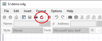
 Cut button removes selected items and places them on the clipboard.
 |
|
||
|
|
|
||
|
|
|
||
|
|
|
||
|
|
|||
Navigating
To pan around either use the scrollbar or position the
mouse pointer over the background of the diagram, hold down the right
mouse button and move the mouse.
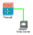
To follow a link to another diagram - Right click the object and select "Goto
next diagram". Objects which link to another diagram have a blue
caption by default.
The toolbar back and forward
buttons may also be used to jump to the previous or next diagram.
The
Home button loads the default diagram if one has been specified in the
Setup form.
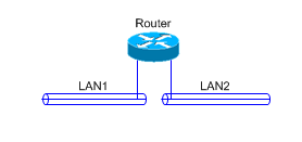
Network Notepad Enterprise Edition supports multi-page diagrams. The
Tab bar along the bottom of the window shows a tab for each page in the
diagram.
Using The Zoom Buttons
-+ Zoom buttons and Zoom Dropdown list lets you quickly zoom in and out the view of the current page. CTRL+Mousewheel also operates the Zoom. You can work on diagrams at any zoom level as normal, though it usually helps when rotating objects and text to return the view to the default 100% scale.
Tip: Right click the Zoom dropdown list to quickly default the view back to 100%.
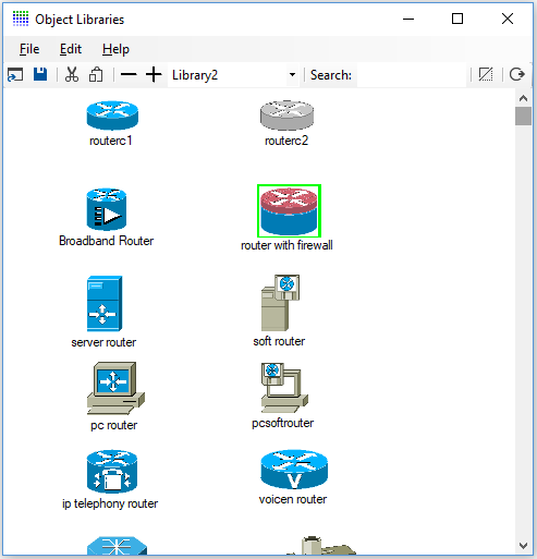
Adding Objects To A Diagram
Click the Object Libraries Button ![]() to display the current Object Library.
to display the current Object Library.
Drag and drop Objects from the Library to the diagram.
You may also paste Library objects by selecting the object
from the library and then closing or minimising it.
Point the cross hair where you want to place the objects.
To automatically hide the Object Library whenever you select a new object,
enable "Auto Hide" in the setup dialogue or from the Object Library
ring menu.
The Paste button performs a single paste operation and exits paste mode. The Paste Multiple button
performs multiple paste operations without exiting paste mode.
The Online Libraries Button
![]() opens a list of objects available online.
opens a list of objects available online.
Tip: Double right click the background to toggle the last used mode (Paste, Text, or Link) off and on.
Cutting And Deleting Objects From A Diagram
Highlight the objects you wish to cut or delete by
left clicking them and then hit the Cut Button ![]() to place them on the clipboard. Click the Delete Button
to place them on the clipboard. Click the Delete Button ![]() on the toolbar to remove selected items.
on the toolbar to remove selected items.
Pressing SHIFT+Delete on the
keyboard is another way to delete selected items.
Selecting/ Deselecting Single/ Multiple objects
Objects need to be selected (Red highlight) and
deselected for cutting and pasting. To select an object, left
click it.
To select multiple objects at once, drag a "rubber band" around them with
the left mouse button.
You must start selection with the mouse pointer positioned over a blank
piece of background.
To select or unselect additional objects, hold the CTRL key down while
selecting.
To select no objects, left click the background or choose Edit and then
Select None from the ring menu. CTRL-A also toggles between
selecting all and selecting none.
Tip: CTRL-A toggles between selecting all and selecting none.
Aligning Objects
To align objects, first select the item to align to
and then select items to be aligned with the first item. Choose Format and
Align Horizontal or Align Vertical from the Ring Menu or click the
horizontal and vertical align buttons
![]() , and then select whether to align centres
or edges of the objects from the sub menu.
, and then select whether to align centres
or edges of the objects from the sub menu.
When pasting objects and drawing links,
objects and lines are automatically aligned if the Auto Align button
![]() is selected.
is selected.
Resizing Objects
Use Shift + and Shift - to adjust the size of
the current object retaining its current proportions.
You can also resize an object by dragging the edge or corners.
Objects can also be resized by changing the x and y scale in the
Object Properties
form or on the Object Properties Toolbar.
Tip: Double right click the background to toggle the last used mode (Paste, Text, or Link) off and on.
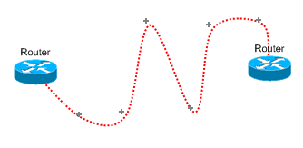
Link AlignThe link align feature converts any sloping link segments on a
link to horizontal and
vertical link segments. Right-click a link and select Align On or Align Off to
switch this feature on and off. |
 |
|
|
 |
|
Layers (Drawing Order)You can control the drawing order for objects, text and links by setting the layer. Layer 5 is drawn first through to layer 0 which is topmost. Set the layer using one of these methods:
|
|
|
Background ObjectsSetting an object to be a background object in the Object Properties form enables you to draw multi-segment links over the top of an object without connecting to it. |
||
Unlinking Objects
To remove links between objects, right-click the link
and choose delete or select the objects which are linked and then click
the Unlink Button ![]() .
.
Using the Link Break Feature
The Link Break Feature enables you to break a link and
create a join anywhere on an existing link. When you right-click the
link and select Break a new "link-node" is highlighted which you
can then drag and drop or nudge to the desired position.
To remove a
join select the link-node which forms the join and delete it.
Moving and Copying Objects
To move selected objects, hold the left mouse
button down on an object for 1.5s and then drag and drop. Alternatively
holding the Shift Key down enables drag and drop immediately.
To copy objects, select them and then click then Copy Button
![]() .
Click the Paste Button
.
Click the Paste Button ![]() to enter Paste Mode and the position the cross hair and left click to
paste copies of the objects. To finish pasting, click the Paste Button
to enter Paste Mode and the position the cross hair and left click to
paste copies of the objects. To finish pasting, click the Paste Button
![]() again, or double right click the background to exit the current mode, or
hit the escape key.
again, or double right click the background to exit the current mode, or
hit the escape key.
Nudging Objects
To nudge selected objects, hold down the Shift key while pressing one of the cursor keys.
Setting An Object's IP Address
To set an Object's IP Address, right-click the
Object and choose "Properties".
Enter the IP address in the Address
field. For more information see Object Properties.
Changing The Name (Or IP Address) Of An Object
To change the name of an object or change its
IP address, Double Left Click on current name or IP address and type in
the new details. Press Enter to complete.
You may also change these details by right clicking the object and selecting
"Properties".
To insert a Carriage Return in an Object or IP Label
use
Shift + Enter.
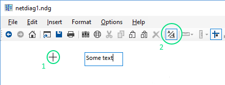
Adding Text To A Diagram
|
Click the Text Mode Button Tip: Double right click the background to toggle the last used mode (Paste, Text, or Link) off and on.
|
|
Editing Text
Double click text to start editing it. The Text Mode
button will indicate you are in text mode. Press ESC to finish editing the text, or click the text mode
button on the toolbar.
To delete a Text Box, double click it and then hit backspace. Press
ESC or click the text mode button to exit text mode.
Formatting Text
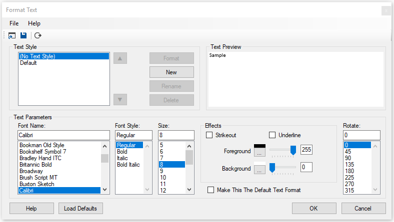
Text Properties Toolbar
![]()
The Text Properties Toolbar is optionally displayed
by selecting Options > Text Properties Toolbar. It provides access
to the properties for the most recently clicked text or if no text is selected
it provides access to properties for the current font which is used when
adding new text.
The controls displayed on the toolbar
are covered in the Format Text section above.
Adding Backbones
|
Add horizontal and vertical backbones to your diagram by selecting them from
the Backbones object library. |
|
Resizing And Moving Backbones
To resize a backbone, position the mouse pointer over either
end then hold the left mouse button down to drag the backbone larger or
smaller.
To move a backbone, hold the shift key down whilst dragging the backbone to
a new position.
Customizing Backbone StylesBackbones are Shapes and they can be customised by right clicking and select Format Shape. |
|
Linking An Object To A Backbone
To link an object to a backbone, click on the link
mode button ![]() and then join the backbone to the object.
and then join the backbone to the object.
Grouping and Locking
Objects may be grouped together and then locked in position relative to each other to form composite objects.
The first object you select will become the "parent" object and further
objects selected will be "child" objects.
Select the parent object, followed by the child objects and then select
Format > Group from the ring menu to group the objects together. At this
point, you may still move the objects relative to each other. Copying and
pasting the parent object will copy and paste all of the child objects as
well.
To lock the child objects position relative to the parent object, right
click the child object and select "Lock" from the menu. Now when you move
the child object, the parent and all of its child objects are moved
together. If you resize the parent object all locked child objects are
also proportionally resized and moved.
Right-clicking a parent object and selecting Lock > Group Lock or Group
Unlock locks or unlocks all child objects and labels associated with the
object.
To ungroup objects, select each of the members of the group and
then click Format > Ungroup on the ring menu.
Example using the two shapes created in the Custom Shapes section to form a composite Title Box object:
|
|
Position the two shapes to form a title box. |
Locking objects which are not a member of a group is used to lock the position of the object on the page. This is useful for things like template borders and title blocks which don't normally need to be moved. Objects locked to the page have the following properties:
- They cannot be moved with drag and drop.
- They cannot be selected with CTRL-A or by dragging a band around them.
Anchoring and Locking
Anchoring fixes the position of objects and text relative to one of
the four corners of the page. This is useful when resizing the
page to ensure a title block and border remain fixed to the edge.
Select objects and text to be anchored and then Format > Anchor from the
menu.
Locking objects and text prevents them from being dragged to a
new position (relative to their parent) and also prevents them from
being selected and unselected using CTRL-A. It is useful if the title
block and border are locked. You can then select your diagram using
CTRL-A and reposition it using drag and drop or nudge, without adjusting
the position of the title block and border.
Select objects (link
nodes) and text to be locked and then Format > Lock or right click
objects or text and select Lock.
Rotating Objects and TextRotate objects and text using any of the following methods:
|
 |
Hiding IP Addresses
To Reveal or Hide IP addresses, toggle the IP Address
Button ![]() .
.
Working With Shared Documents
Network Notepad Enterprise Edition includes features which enables multiple users to edit shared documents/ diagrams safely. It solves the problem where a document which is edited simultaneously by more than one user results in changes made by one user being overwritten by another user.
| In the Setup form,
first make sure all users have a unique User Name assigned. (Do not tick/check the "All Documents Shared" checkbox for now. See the Setup Form section for more information about this.) |
 |
|
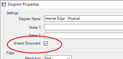
To make the current document shared, tick the shared document box in the Diagram Properties Form. |
 |
|
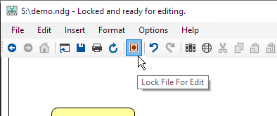
| A shared document is initially opened in read-only mode. All edit functions are disabled until the user clicks the Lock File Button. |
 |
|
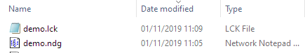
| A "lock file" is created along side the document file. It stores the name of the user who has locked the file and the time and date the lock was created. |
 |
|
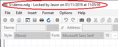
| Other users who have the document open will see the status displayed in the title bar. They are blocked from editing the document until the lock file is released. |
 |
|
| To release the lock click the Lock File button again. The document is automatically saved. | ||
| The status is reflected in the title bar for other users and the refresh button changes colour to red to indicate an update is available. |
 |
|
| Clicking the refresh button reloads
the document. Locking the document automatically refreshes the document first if the diagram has been updated by another user. |
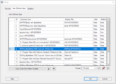
User-Defined Apps
A list of user-defined Apps is presented for execution
when you right click an object. The first 6 of the Apps are also
available using the function buttons on the main toolbar:
![]() .
Variables such as IP address or hostname of the object can be included
in the App definition.
.
Variables such as IP address or hostname of the object can be included
in the App definition.
A set of user-defined Apps is called a
toolset. Multiple toolsets can be configured for use with
different types of equipment and then assigned to the objects in your
diagram from the Object Properties form.
Configuring User-Defined Apps |
|||
|
|
 |
||
|
Examples:
Tip: Enclose file pathnames containing spaces with quotation marks as shown in the first three examples above. If you don't do this then Windows cannot distinguish the difference between c:\program files and c:\program.exe for example. Copy Tools From Other Toolsets: When creating a new toolset you can use this option to list all tools in all toolset and tick those you wish to copy to the new toolset. Up/ Down Buttons: Change the
order the tools are presented by moving the selected tool up or down in
the list of tools. Add Toolset Button
Edit Button
Toolset(0)=1. Routers When editing the tooldefs.txt file keep the numbers in
brackets in order. That is the is (toolset number) in the case of the
Toolset statement and (toolset number, tool number) in the case of the
Command, Display,Automin and Multiple statements. Refresh Button
|
|||
|
 |
Searching DiagramsTo search a diagram, press CTRL-F to display the find dialog.
Enter the text to find in the text box. |
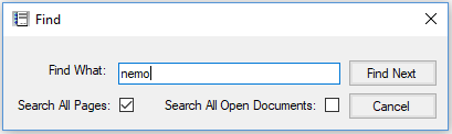 |
Tip: Network Notepad Files are stored as plain text. Use Windows "Search for Files" to scan through all your diagrams and find what you are looking for.
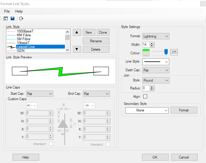
Customizing Link Styles
Select Format > Link Styles on the ring menu or right-click a link and select Format Link style.
|
|
|||||
|
Style Settings
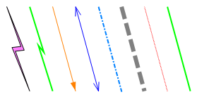
Format: Choose between Line, Lightning, Lightning2,
Curve and Curve2 Styles. For the Lightning style to be effective set the width to 14 or more.
You can override the link style setting for individual links to switch between
Line, Curve and Curve2 from the link context menu (right-click link). Line Caps
Startcap, Endcap: Selects from a range of built-in startcap/ endcap and
custom startcap/ endcap styles. The appearance of the former is dependent on the
width of the link and hence is fairly limited. Selecting Custom
startcap/ endcap gives much more control over the appearance. The graphic in the
centre shows how the X,Y,W and
H custom cap parameters control
the dimensions and position of the cap.
Load Defaults: Wipes all of the link styles and loads a new
set from the linkdefs.nls file. If you delete a link style which is used in
the diagram the link is draw using a dashed red line. |
|||||
Curve Link StyleCurved link styles use one or two link nodes to act as control points for
the curve. From the ring menu select "Options" and "Show Link nodes" to
display link nodes while you are drawing curves. |
 |
Curve2 Link StyleCurve2 Link Style allows you to draw curved Links with any number of
control points.
|
|
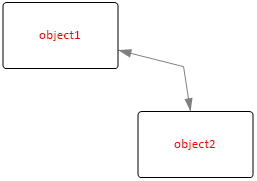
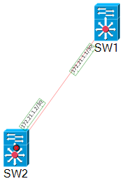
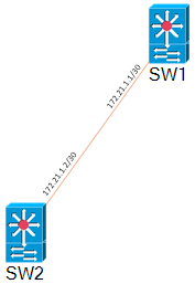
Attaching Labels To Links
|
When labels are attached to
links, they are rotated automatically to follow the slope of the link. |
 |
How To Attach Labels To A Link
 |
 |
 |
 |
|
1. Place labels in approximate positions using the text tool. |
2. Select the link first (black/red circle indication at link termination point) then select each of the labels. |
3. Click Format and then Group. The labels are grouped with the link and are automatically rotated to follow the slope of the link segment. Selecting the link now also highlights the related labels. |
4. Finalise label positions using Drag and Drop or nudge. |
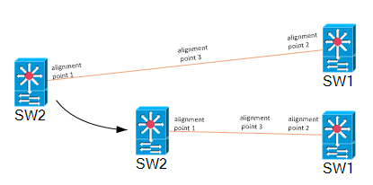
Alignment PointsThere are three alignment points on a
link segment, one at each end and one in the centre of the
link segment. The position of a label is relative to the
nearest alignment point when the label was first grouped
with the
link. Detatching A Label from A LinkTo detach a label from a link,
right-click the label and click Ungroup in the context menu. |
 |
THE OBJECT PROPERTIES FORM |
|
 |
Linking Diagrams
Diagrams may be linked together such that one or more special objects in a
diagram provide a link to other pages or files. To follow a link to another
diagram, right click the object and select "Goto next diagram" or double click
the object. To configure an object to link to another page or file use the
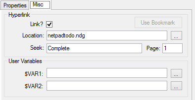
following settings on the Misc Tab in the Object Properties form:
Link?: This tick box enables the "Goto next diagram"
option when this object is right clicked.
Location: Filename of next diagram (include .ndg
extension). Leave this blank for the current diagram.
Page:
Optional page to open in the next diagram.
Seek:
Optional text to seek and centre-on when the next diagram is loaded.
Use bookmark: Completes the Location, Seek and Page fields with the
last bookmarked location (Edit > bookmark).
Example
We will link an object on page1 to an object on page
3:
Go to destination object on page 3.
Right-click the object and
click "Bookmark Object".
Go to the source object on page
1.
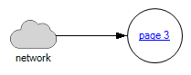
Open it's Properties and select the "Misc" Tab.
Tick the "Link" box, click "Use Bookmark" and then click OK.
You
can now right-click the object on page 1 and click "Go To Next
Diagram".
To create a link back the
other way, bookmark the object on page1 and add it to the properties
of the object on page 3.
|
|||||||
Drag And Drop Method For Linking Diagrams
Another way to create a link to a diagram is to drag and drop the .ndg file you want to link to on to the canvas of the current diagram. This adds an object which provides the link as discussed above.
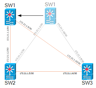
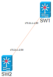
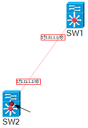
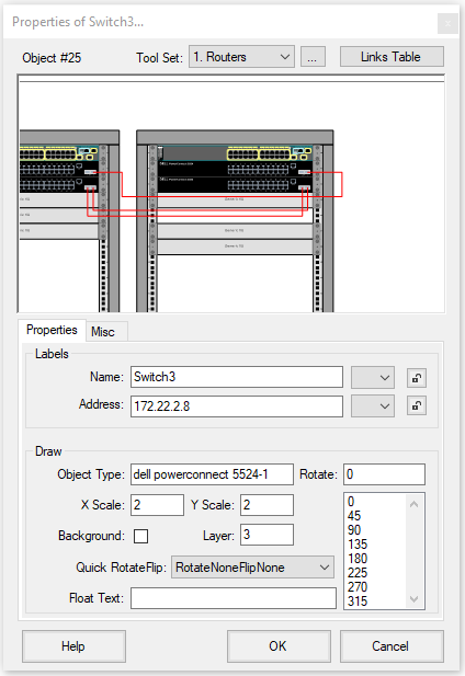
The Links Table
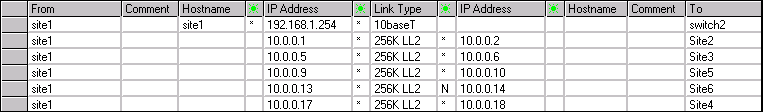
|
The links table shows a table of all the connections to an object.
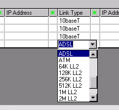
Changing Link StylesTo change a link's style in a diagram right click the link and choose "Set
link style". You may also change a link style from the Links table by clicking a
cell in the Link Type column and choose the new link style from the drop down
list. |
|
Object Properties Toolbar
The Object Properties Toolbar is optional. It provides quick access
to some of the properties for the most recently clicked object.
Enable the toolbar by selecting Options > Object Properties Toolbar
from the main ring menu.
The controls displayed on the toolbar
are covered in the Object Properties Form section above.
THE OBJECT LIBRARY FORM |
|
Searching Object LibrariesThe search box on the toolbar may be used to search all available libraries
for objects. Adding Objects To An Object LibraryDrag a .ico, .bmp, .wmf, .gif, .png or .jpg file
on to a blank part of the Object library form. Right clicking an object allows you to change an
objects default name, filename and X/Y scale. Deleting Objects From The Object Library FormTo delete an object from the current Object Library, select the object followed by "Edit" and "Cut Image from Object Library". Auto-Hiding The Object Library FormTo auto-hide the Object Library Form whenever an object is selected
click File > Auto-hide. |
 |
Creating New Object Library Files
From the Object Library ring menu select File>New to create a new, blank Object Library file. Paste new object images as explained previously and then use File > Save As to save the new Object Library.
Sharing Object Library Files
A workgroup Object Library (Folder) may be specified in the main
setup form. Network Notepad will use this library when the shared drive
is available. Otherwise it will use the default local copy.
To set this up initially, copy contents of the local objects folder to the
shared folder.
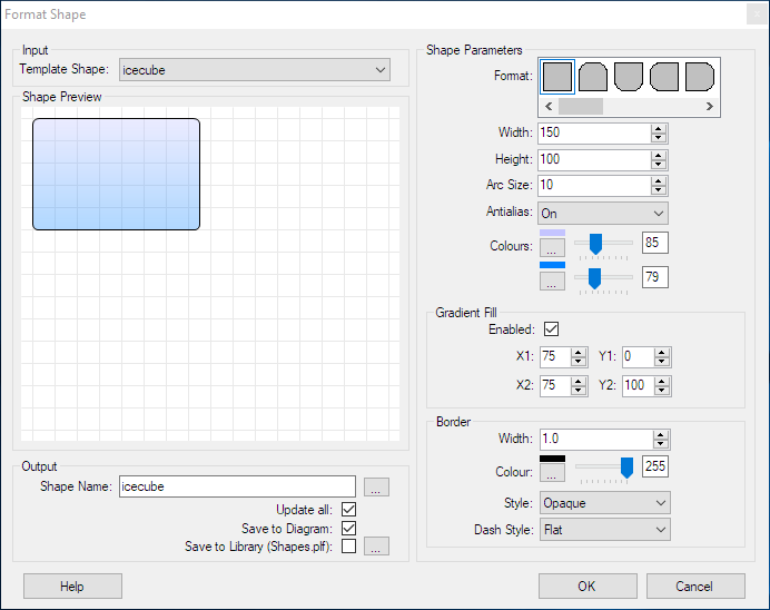
CREATING CUSTOM SHAPES |
Shapes are simple graphics which can be customised. There are some
shapes preconfigured in the "Shapes" and "Backbones" Object Libraries.
Select Format > Shape from the main ring menu or right click a shape in
a diagram or Object Library.
Format Shape
|
Template Shape: Is
a list of shapes populated from the current diagram or library. The selected
shape is used as the starting point for further customization. |
Example Shapes |
||
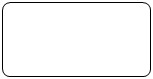 |
Rectangle, Width=200, Height=100,
background set to transparent by setting the colour slider control to
the left. Arc size 20 sets radiused corners. |
|
|
|
Rectangle, Width=200, Height=100. This variant has only the top two corners radiused. |
See Grouping and Locking for information on combining these shapes in to a composite object.
SCRIPT OBJECTS |
"Script Objects" provide a way to construct vector-based
graphics
for use in Network Notepad from plain-text scripts. Some examples
are available in the
scripts library.
Script Syntax
A Script Object consists of the following statements and commands:
1. The Script Statement.
2. Path Statements.
3. Pens and Brushes.
4. Commands.
5. Align Statements.
1. The Script Statement |
||
| script | The script statement sets the name, the overall size of the object, and the revision number. | |
| script name width height revision | ||
| name - name of the script object. If the name contains spaces then enclose it in "quotation marks". The name should be globally unique. | ||
| width - width of the object. | ||
| height - height of object.The width and height set the
size of the outline box displayed when pasting the object. In the examples I am using a default scale of 1pixel per mm. |
||
| revision - Revision number of the script. When pasting scripts which already exist in the diagram, the script will only be replaced if the new script is a higher revision. | ||
script "Test object" 50 20 0.1 |
||
2. Path statements |
||
| path | Path statements define the shapes, lines and text in the object. | |
| path name
name name - name of graphics path. |
||
| path startfigure Starts a new path rather than continuing the current path. |
||
| path addline
x1 y1 x2 y2 Adds a line to the current path. |
||
| path addlines
x1 y1 x2 y2... xn yn Adds a series of lines to the current path. |
||
| path addrectangle
x1 y1 width height Adds a rectangle at the position specified with the width and height specified. |
||
| path addarc
x y width height start-angle sweep-angle Adds an arc to the current path. x y width height - define a rectangle which forms the bounds of the arc. start-angle - measured in degrees clockwise from the x-axis. sweep-angle - angle swept from start angle. |
||
| path addstring
x y "text" font-name font-size font-style Adds a text string to the current path. x y - specify the top left corner position of the text. "text" - text string to draw. font-name - Name of font. Enclose in quotation marks if the font name contains spaces. font size - Font size. font style - Numeric value, Regular=0, Bold=1, Italic=2, Underline=4, Strikeout=8 Add font style values to combine them e.g. Bold+Italic+Underline =7 Use a fill command rather than a draw command to render text. If you use a draw command the outline of the text is drawn. |
||
| path closefigure Closes a path by extending it to the start point in the path. Example path statements: path name module path addrectangle 0 0 77 40 path name vent path addarc 0 0 6 6 90 180 path addarc 38 0 6 6 270 180 path name "SFP Slot" path addrectangle 0 0 14 9 path name label path addstring 0 0 "SFP" arial 2.25 1 path name screw path addarc 0 0 8 8 0 360 path name screwhead path startfigure path addlines 3 2 2 3 3 4 2 5 3 6 4 5 5 6 6 5 5 4 6 3 5 2 4 3 path closefigure |
||
3. Pens and Brushes |
||
| pen | Pen statements set the colour and thickness of a line when used with the draw command below. | |
| pen name colour transparency
width name - name of the pen. colour - Blue green and Red values in Hex. transparency - Number from 0-255 where 255 is solid colour. width - width of line drawn with the pen. pen black_pen0.5 &h000000& 255 0.5 draw outline black_pen0.5 |
||
| brush | Brush statements set the colour used with the fill command below. | |
| brush name colour
transparency Brushes are used with fill commands to fill an area enclosed by a path. name - name of the brush. colour - Blue Green and Red values in Hex. transparency - Number from 0-255 where 255 is solid colour. brush grey_brush &ha0a0a0& 255 fill body grey_brush |
||
| gradientbrush | A gradientbrush is used to fill an area enclosed by a path using a brush which transitions from one colour to another. | |
| gradientbrush name colour1
transparency1 colour2 transparency2 width height angle name - name of the gradientbrush. colour1 - starting colour in hex. transparency1 - Number from 0-255 where 255 is solid colour. colour2 - Ending colour in hex. transparency2 - Number from 0-255 where 255 is solid colour. width, height - define the size of the brush. angle - direction of gradient. gradientbrush cloudbrush &hE4E4E4& 255 &h646464& 255 1 62 90 fill cloudpath cloudbrush |
||
4. Commands |
||
| draw | Draw the outline of a path using the specified pen. Draw at position x y and apply an optional local scale transform and/or rotate transform. | |
| draw path pen x y [xscale yscale]
[angle] path - name of path to draw. pen - name of pen to use. x y - position of drawing. xscale yscale - scale transform. Negative values are used to flip the drawing about the x or y-axis. angle - optional rotation angle in degrees (introduced in version 1.3.11). draw "top box" black_pen0.5 20 10 |
||
| fill | Fill an area enclosed by a path using the specified brush. Draw at position x y and apply an optional local scale transform and/or rotate transform. | |
| fill path brush x y [xscale yscale]
[angle] path - name of path to fill. brush - name of brush to use. x y - position of drawing. xscale yscale - scale transform. Negative values are used to flip the drawing about the x or y-axis. For an example of this see the left and right brackets in the 2960 switch which use the same path but flipped about the y-axis. angle - optional rotation angle in degrees (introduced in version 1.3.11). fill test "grey brush" 20 10 |
||
| paint | Enables a Script Object to include other Script Objects in it's drawing. | |
| paint script x y [xscale
yscale] script - The name of the script object to draw. It must be present in the current diagram's table of Script Objects. x y - The coordinates of the Script Object. xscale yscale - Optionally draw the Object Script using non-default scale values. (The paint command was introduced in version 1.3.36) paint "RJ45 Socket" 50 20 |
||
| texturefill | Fills a path using
another script as the brush. |
|
| texturefill path
script
[x y] [xscale] [yscale] [angle] path - name of path to fill. script - name of script to use as a brush. x y - position of drawing. xscale yscale - optional scale transform. angle - optional rotation transform. texturefill ventarea ventscript9 |
||
| option | The option command is followed by optional fill, draw and paint statements which can be enabled or disabled at run-time by right-clicking the object and choosing "Options". E.g. See the brackets and screws options in the 2960 switch example. | |
| option name
[optional mask] name - provides the text which will be displayed in the options menu. mask - This option controls how the entries in the options menu work. Without a mask or with a mask value 0 you can switch any option on or off. With a mask the options covered by the mask are mutually exclusive. You can select one option only from the masked options and at least one of those masked options must be selected. In the example below the first 3 options are grouped using the mask value 7 and allow you to choose a background colour. The next two options are grouped using mask value 24 and allow you to choose a border colour. The mask values are derived from the order the options are read in and assigned a bit value. The first 3 options correspond to bits 0-2 which gives a binary value 111 and mask value 7. Bits 3-4 give a binary value 11000 and mask value 24. The option end statement enables drawing to continue after the options. option end "option end" is a special case. It is not displayed in the options menu and merely permits normal drawing to continue after options. script "cloud7 with options" 100 70 1.6 pen red_pen &h0000ff& 255 1 pen blue_pen &hff0000& 255 1 brush grey_brush &hD4D4D4& 255 brush red_brush &h9595FF& 255 brush yellow_brush &h16E3E9& 255 brush black_brush &h000000& 255 path name cloud path addarc 0 22 40 40 278 -188 path addarc 60 22 40 40 90 -160 path addarc 52 8 35 35 -10 -102 path addarc 23 1 40 40 330 -153 path name text path addstring 27 32 "The Cloud" arial 7 1 option "background grey" 7 fill cloud grey_brush option "background red" 7 fill cloud red_brush option "background yellow" 7 fill cloud yellow_brush option "border red" 24 draw cloud red_pen option "border blue" 24 draw cloud blue_pen option end fill text black_brush |
||
| antialias | Switches antialiasing off or on. The default setting is on. | |
| antialias off | on off - switch off antialiasing. on - switch on antialiasing. |
||
5. Align Statements |
||
| align | Align statements optionally enable objects to be automatically aligned when one object is pasted or dragged and dropped on to another object. | |
| align +|- type points +|-. A "+" script can only align with a "-" script. type - For scripts to align the type must match between the two scripts. points - A list of X Y alignment points. align + screw -11 6 454 6 -11 50.5 |
||
Format Script Object
Format Script Object provides an environment for creating and modifying Script Objects. Access it from the Format menu or right-click a Script Object in a diagram or the library window.
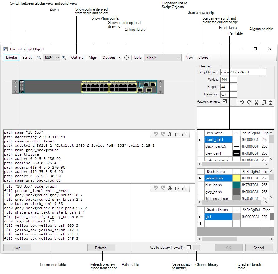
To paste a script in to the editor, switch to script view
(Script button) and paste in to the main panel.
Colour
Pickers for pens and brushes are available in the Tabular view
by clicking the elipsis column (...) in the
respective tables.
&hBbGgRr& specifies the Blue, Green and Red
components of the colour in Hex.
Tspcy is the colour
transparency value from 0 to 255, where 255 is solid colour.
The form is resizable and the panels can also be resized by dragging
the horizontal and vertical bars which divide the panels.
Click the Refresh button to apply changes made in the script panels.
Merging Script Objects
Format > Merge Script Objects enables
mulitple Script Objects to be merged in to a single Script Object. Text can
also be merged.
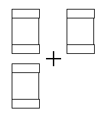
In the following example an small ethernet hub is built up
from components in the online Script Objects Library and then merged:
1. Add the parent object which will act as a container for the
other components.
I have used Format Script Object to create a
box and given the script a new unique name (this is important).
|
|
script "Netgear FE104" 158 25 0.5 brush blue_brush &h8B4001& 255 path name Box path addrectangle 0 0 158 25 fill "Box" blue_brush |
2. Copy and paste script components from the
online library on to the parent object.
I have added four RJ45
sockets and then using the Text tool added a brand label.
![]()
3. Put the parent box and child components in to a
group.
Select the parent Box first followed by the 4 sockets and
the label, then select Format > Group on the ring menu.
The
objects are now loosely bound together.
![]()
4. Select the group by clicking the parent box
and then select Format > Merge Script Objects.
The parent box and
the 5 child objects are now merged into a single Script Object.
|
|
script "Netgear FE104 Hub" 158 25
0.6 brush blue_brush &h8B4001& 255 brush black_brush &h000000& 255 brush silver_brush &hd0d8dc& 255 brush brush1 &hFFFFFF& 255 path name Box path addrectangle 0 0 158 25 path name rj45down path addlines 2 7 2 9 3.5 9 3.5 10 9 10 9 9 10.5 9 10.5 7 12.5 7 12.5 0 0 0 0 7 path name single_port path addrectangle 0 0 15 12 path name path1 path addstring 0 0 NETGEAR arial 3 1 fill "Box" blue_brush fill single_port silver_brush 111.5 8 fill rj45down black_brush 112.5 19 1 -1 fill single_port silver_brush 66.5 8 fill rj45down black_brush 67.5 19 1 -1 fill single_port silver_brush 81.5 8 fill rj45down black_brush 82.5 19 1 -1 fill single_port silver_brush 96.5 8 fill rj45down black_brush 97.5 19 1 -1 fill path1 brush1 5.25 2.25 |
5. To save the new object to the current local library, right-click the object and select Format Script Object. Click the "Save to Library" checkbox and click OK.
Please email me a copy of your new scripts (or any new components) for inclusion in the online library!
There are a number of restrictions with the
Merge Script Objects feature:
-
The component objects must not be rotated.
-
The component objects must use their default x-scale and y-scale settings (That will be 1,2 or 4 depending on the Format > Resolution setting).
-
Name and Address labels are excluded from a merge.
THE SETUP FORM |
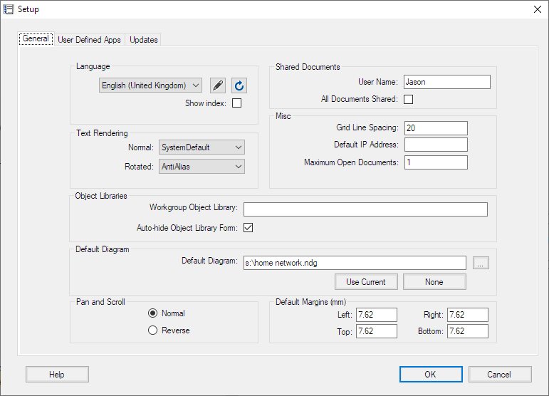 |
The Setup Form
To access the Setup Form select File > Setup from the main ring menu.
General Settings Tab
Language: Select the Language used for Network Notepad.
![]() :
This button opens the selected language translation file for editing.
:
This button opens the selected language translation file for editing.
![]() :
This button refreshes translations from the language translation file.
:
This button refreshes translations from the language translation file.
Show index: To assist with language translations this
temporarily prepends entries with section number and line number to show where
each text entry is located in the language translation file.
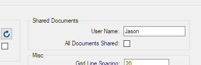
User
Name: Sets the name stored in lock files to show other users who is
editing a shared document. The name must be unique.
All Documents Shared: When this option is enabled,
all documents are automatically set as shared
documents which must be locked before they can be edited. For finer control, set
individual documents to be shared in the Document Properties form.
Grid Line Spacing: Sets
the spacing for grid lines when grid lines option is switched on
("Options","Grid Lines").
Default IP Address:
A partial or complete IP Address which will be applied to all new objects
added to the diagram.
Maximum Open Documents: Sets how many documents can be
opened at once. Each open document presents its own tab bar at the bottom of the
screen.
Default
Diagram: Sets the diagram loaded by default if no diagram is specified
on the command line. Use the ellipses button to browse for a file or the
"Use Current" button to make the current diagram the default diagram. The "None"
button clears the default diagram.User-Defined Apps Tab
For information on the User-Defined Apps, see User
Defined Apps.Updates Tab
Enable Automatic Updates: Tick to enable
automatic updates (default).
Update Type: Select from Automatic, Check and Download, and Check
only.
Manual Proxy Settings: Tick to enable automatic updates with manual proxy server settings.
THE DIAGRAM PROPERTIES FORM |
|
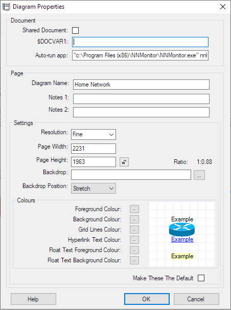 |
TEMPLATES |
Templates
When you start a new drawing or add a new page to an existing document,
you are prompted to select from a list of templates. A diagram template is
simply a minimal diagram which contains defaults for the new drawing. It
sets the page width and height and orientation, default font, link
styles and it can contain some default drawing, for example a title block
and border.
Creating Diagram Templates
To create new diagram template, set up a new single page document with
the desired settings and default drawing as mentioned above and then save it
to the templates folder using File > Save to Templates.
MISCELLANEOUS |
Adding A Backdrop Image
Drag and drop a bitmap file (.bmp, .png, .gif or .jpg) on to the page
to use as a backdrop image for your diagram.
In the Diagram Properties form, you may also specify a filename for a
backdrop bitmap, and you can select whether to stretch, centre or tile
the image.
Export To Bitmap Graphics File
To export a diagram as a bitmap file, from the ring menu, select File and then Export To Bitmap Graphics File. Enter a suitable filename when prompted. The following bitmap file types can be selected from drop-down list: .bmp, .gif and .png.
Export To A PDF File
To export a Network Notepad diagram or document to a
searchable PDF file:
File > Export To PDF > Export
Page or Export Document
Setting A Default Diagram
You may configure a default diagram to be displayed when Network Notepad is
run. The default diagram is configured in the Setup Form.
Working with CSV files
Network Notepad can save to and load from .csv files which means you
can use a spreadsheet to view and edit diagram files.
In the File
> SaveAs and File > Open dialogs select .CSV file in the type
dropdown list.
Import CSV Data
This feature lets you import a list of Objects from CSV data. Open the form from the menu option File > Import CSV Data.
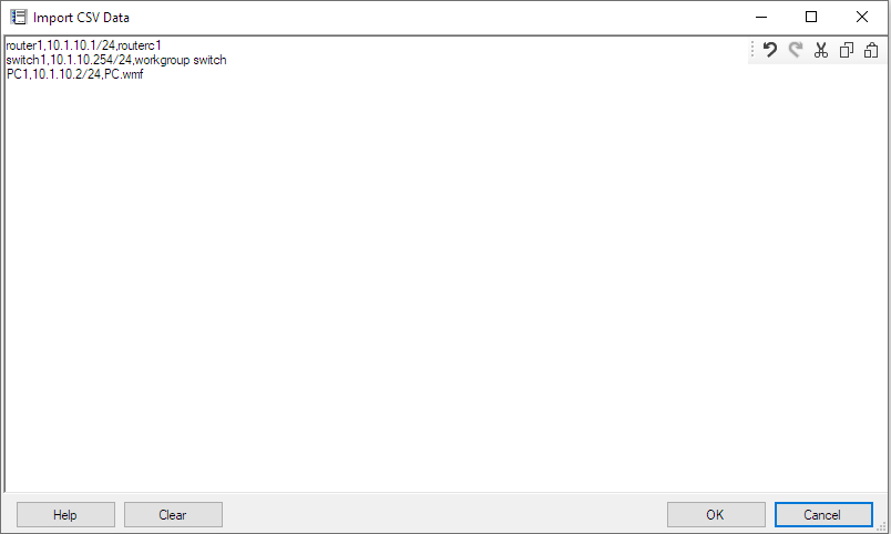
Paste a list of objects in the form in the following format:
Name, Address, Object Type
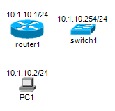
Example:
router1,10.1.10.1/24,routerc1
switch1,10.1.10.254/24,workgroup switch
PC1,10.1.10.2/24,pc.wmf
When you click the OK button, Network Notepad switches to paste mode and shows the outlines of the objects to be pasted
Paste the objects to complete the operation.
Transfer License To Another PC
When a licensed PC is to be replaced, the Network Notepad license can be transferred to the replacement PC using the procedure shown below. There are a couple of points to be aware of when doing this:
-
It is a one-way procedure. You cannot transfer a
license back to the original PC. It is possible to reactivate the
license on the original PC but only with assistance from
Support.
-
As soon as you proceed with the transfer, Network
Notepad will no longer be licensed and will not function the next time
you try to open it.
-
Web browser access to the Internet is required to
create the replacement license file.
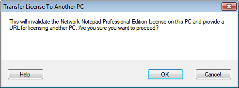
1. On the PC which is to be replaced, open the Network Notepad License Manager and click File > Transfer License To Another PC.
|
2. Click OK at the first confirmation dialog. |
 |
|
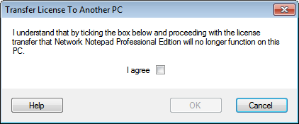
3. Tick the "I agree" box and click OK at the second confirmation dialog. |
 |
|
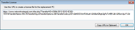
4. Copy the URL displayed to a PC with Internet access and browse to the URL (If you happen to close the dialog at this point, the URL will be displayed again next time you open the License Manager). |
 |
|
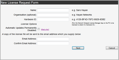
5. Fill out the online form and enter the Hardware-ID from the new PC (Run the License Manager on the new PC to display its Hardware-ID) and click Next. |
 |
|
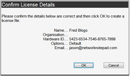
6. Confirm the details on the next page. |
 |
|
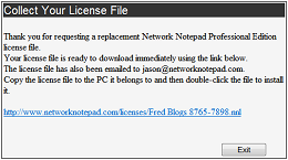
7. Download the new PC's license file. A copy is also sent to the email address entered in to the form previously. |
 |
|
8. Copy the license file to the new PC and double-click the file to install it or use the License Manager menu option File > Install a License File. |
|
© Copyright
J.A.Green |